1. System Overview & Diagram
Below is the detailed IP allocation table for the Lab environment:
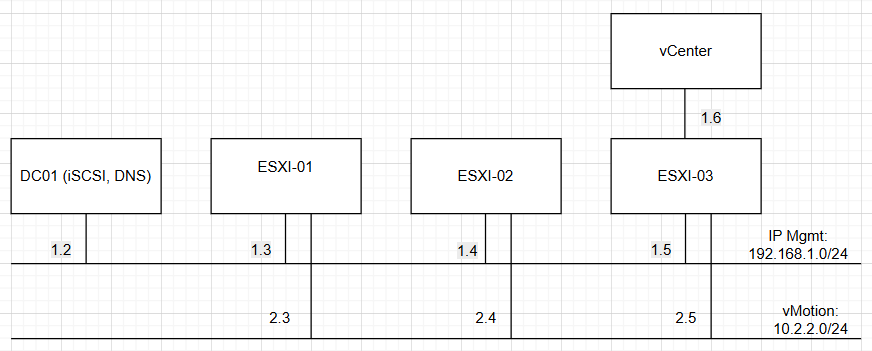
| No. | Machine Name | Hostname | Manager IP (Card Bridge) | vMotion IP (Card VM3) |
|---|---|---|---|---|
| 1 | DC01 | lab.local | 192.168.1.2 | – |
| 2 | esxi-01 | esxi-01.lab.local | 192.168.1.3 | 10.2.2.3 |
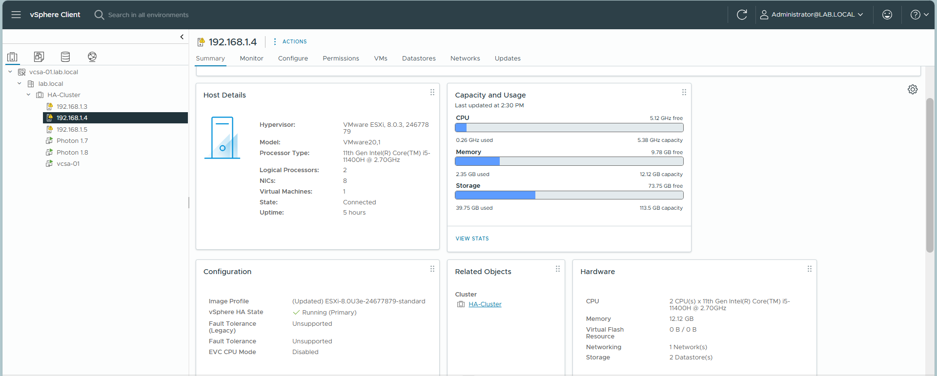
| 3 | esxi-02 | esxi-02.lab.local | 192.168.1.4 | 10.2.2.4 |
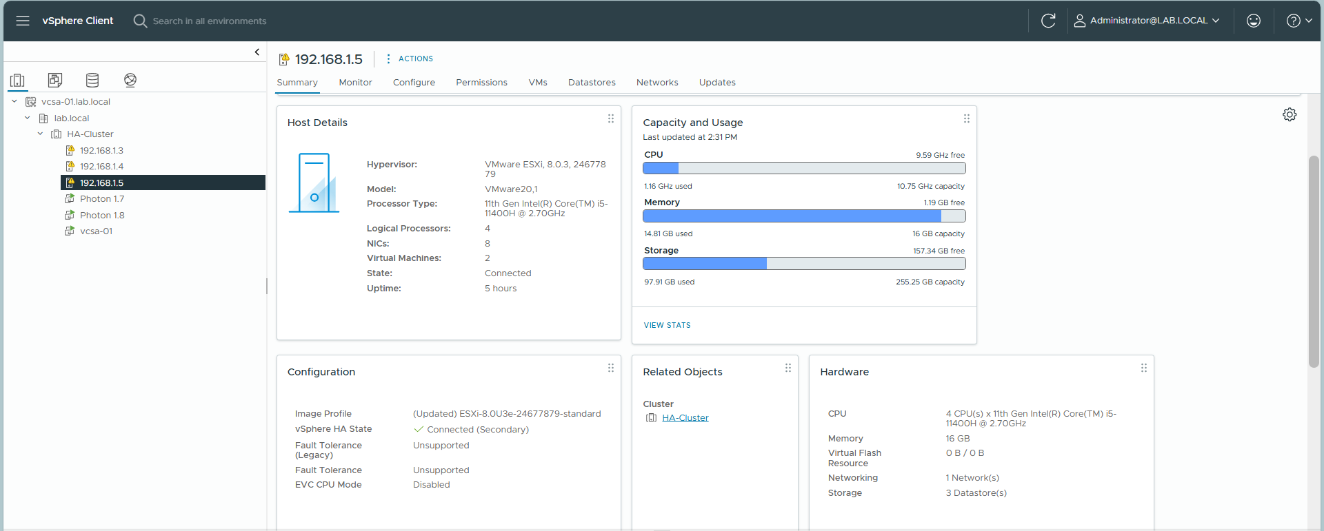
| 4 | esxi-03 | esxi-03.lab.local | 192.168.1.5 | 10.2.2.5 |
| 5 | VCSA-01 | vcsa-01.lab.local | 192.168.1.6 | – |
System Diagram
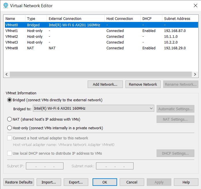
Virtual Network Editor Setup
Ensure your VMware Workstation network is configured correctly (Bridged Mode for external access, and Custom VMnet for internal traffic if needed).
2. Windows Server Configuration (DC/DNS/iSCSI)
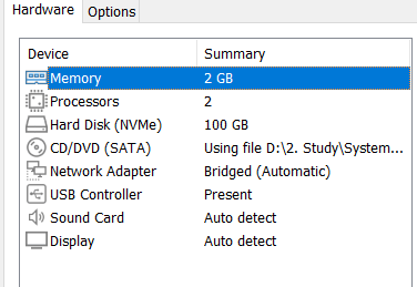
2.1. VM Settings
Recommended settings for the Windows Server VM:
- Memory: 2GB
- Processors: 2
- Hard Disk: 100GB
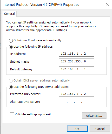
2.2. Network Configuration
Configure a Static IP for the Windows Server:
Subnet mask: 255.255.255.0
Default Gateway: 192.168.1.1 (Point to your router’s gateway)
DNS: 192.168.1.2 (Point to itself)
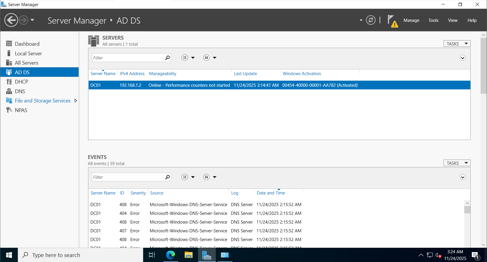
2.3. Active Directory Domain Services (AD DS)
Install the AD DS role and promote the server to a Domain Controller. Create a new forest/domain named lab.local.
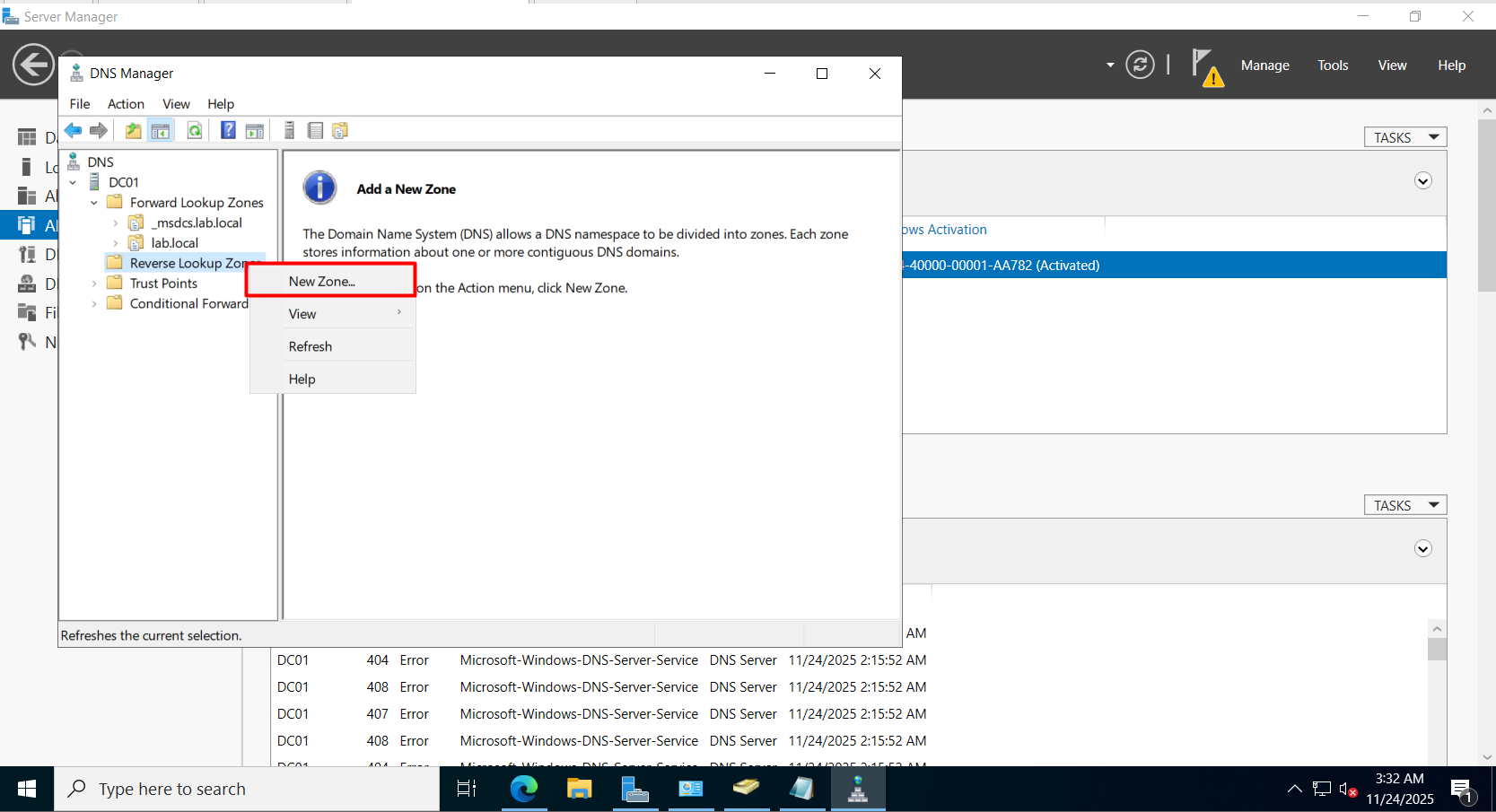
2.4. DNS Manager Configuration
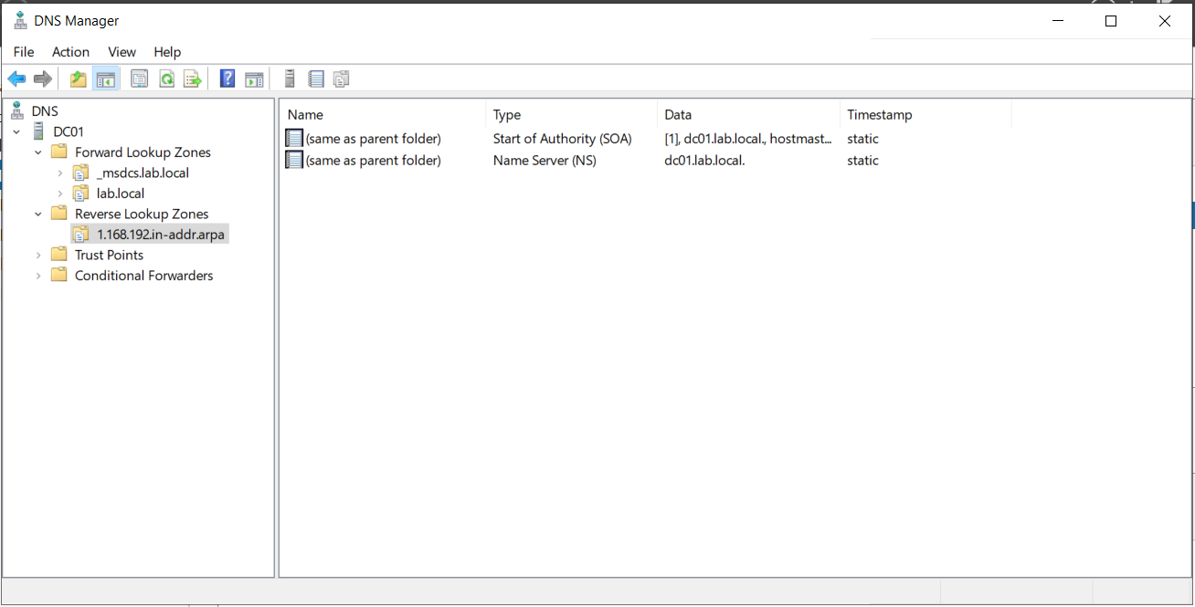
Step 1: Create Reverse Lookup Zone
- Open DNS Manager.
- Right-click Reverse Lookup Zones -> Select New Zone.
- Follow the wizard.
Enter Network ID: 192.168.1
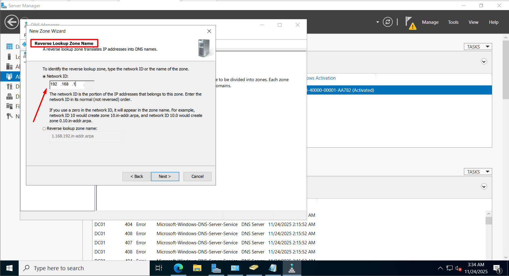
Result: New zone 1.168.192.in-addr.arpa is created.
Step 2: Configure Forward Lookup Zones
- Select zone
lab.local. - Double click the
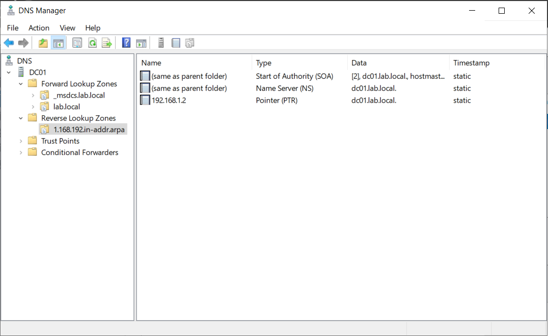
dc01record. - Check the box: Update associated pointer (PTR) record.
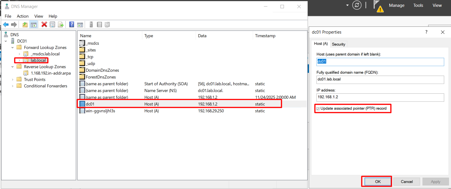
Result:
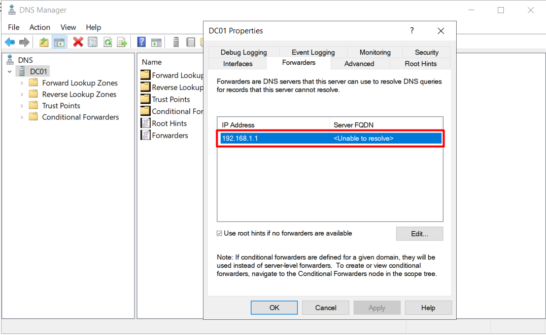
Step 3: Internet Access (Forwarders)
If you cannot access the Internet after setup, check the Forwarders configuration.
- Right-click DC01 -> Properties -> Forwarders tab.
- Add Google DNS (8.8.8.8) or your router’s IP (192.168.1.1).
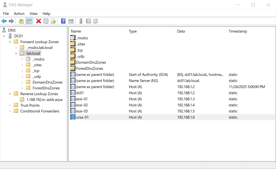
Step 4: Create Host Records for ESXi
Create A records for all ESXi hosts (esxi-01, esxi-02, esxi-03) pointing to their respective IPs.
Righ Click lab.local -> Choose New Host (A or AAAA)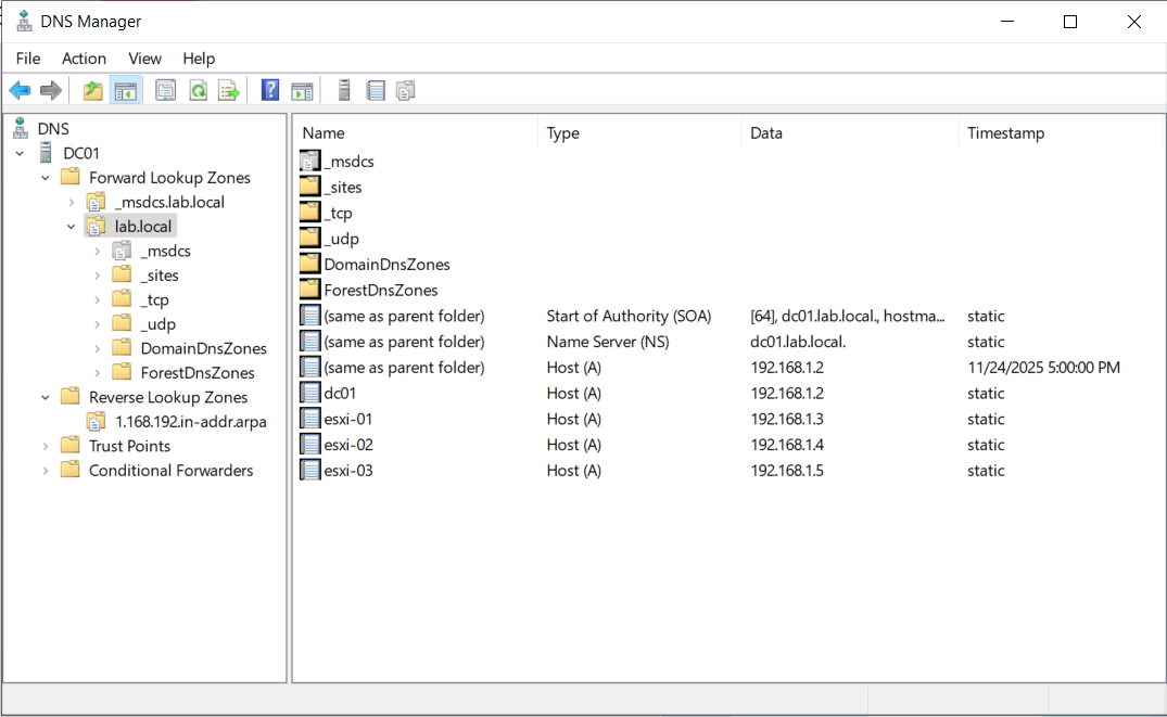
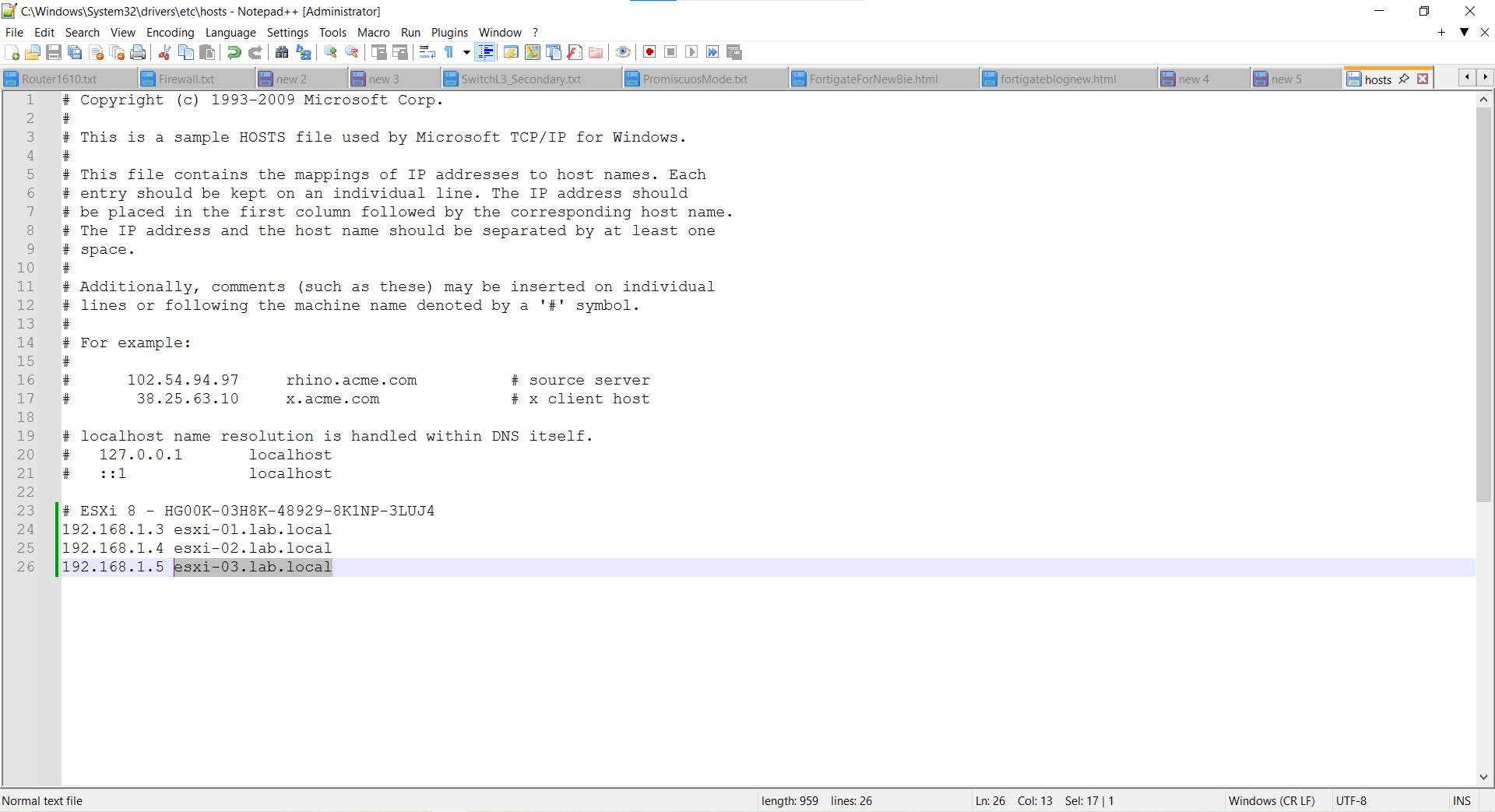
C:\Windows\System32\drivers\etc\hosts):
# ESXi 8
192.168.1.3 esxi-01.lab.local
192.168.1.4 esxi-02.lab.local
192.168.1.5 esxi-03.lab.local
# vCenter
192.168.1.6 vcsa-01.lab.local
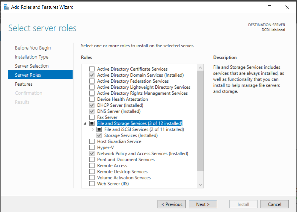
2.5. Configuring Shared Storage (iSCSI)
Prerequisites: Install “File and iSCSI Services” role via Server Manager.
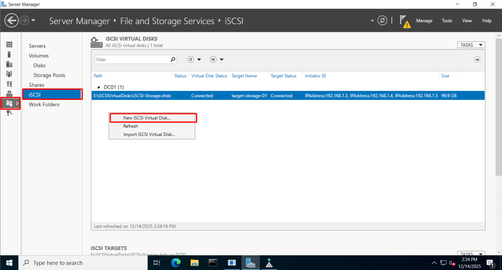
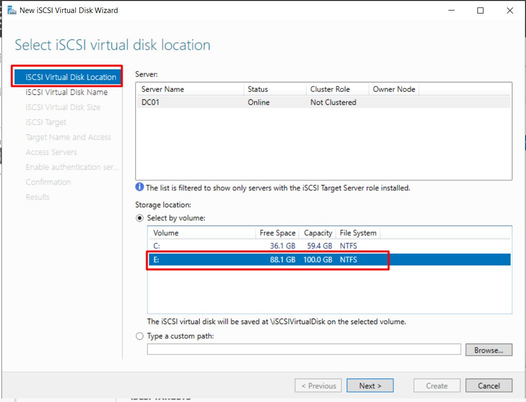
Step 1: Create iSCSI Virtual Disk
Go to File and Storage Services -> iSCSI -> New iSCSI Virtual Disk.
Select the volume to store the disk (e.g., E: drive).
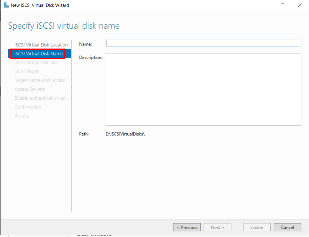
Name the disk (e.g., iSCSI-Storage).
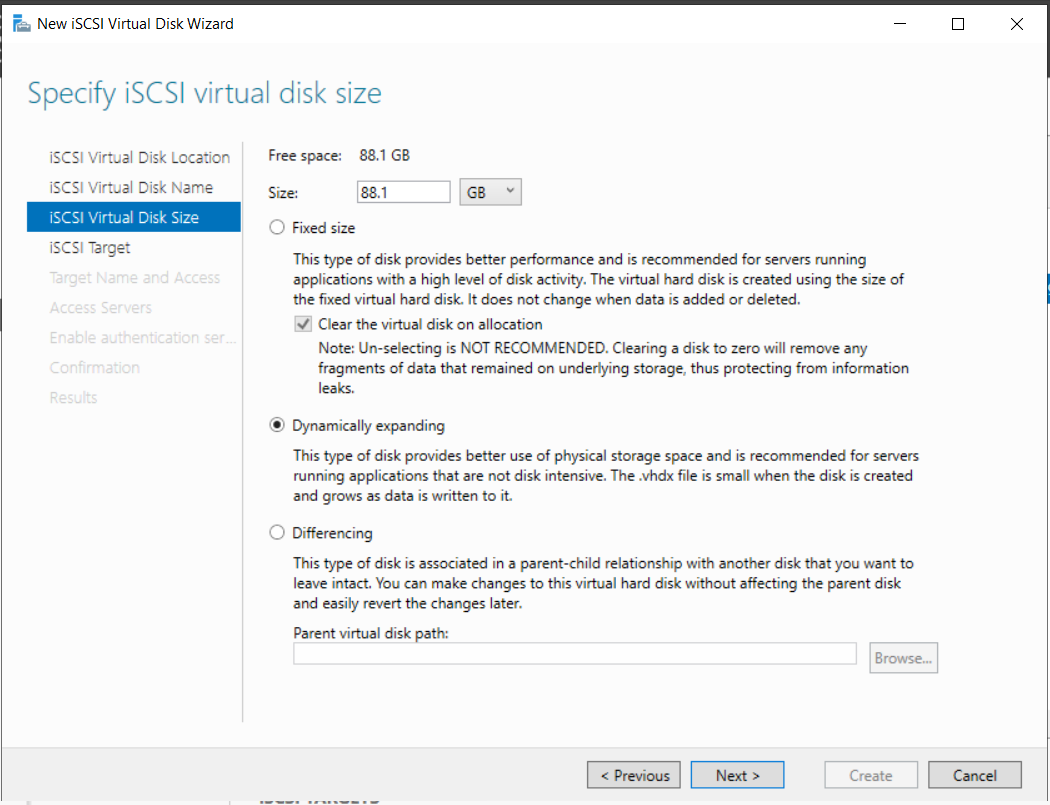
Specify Size (e.g., 88.1 GB) and choose Dynamically expanding.
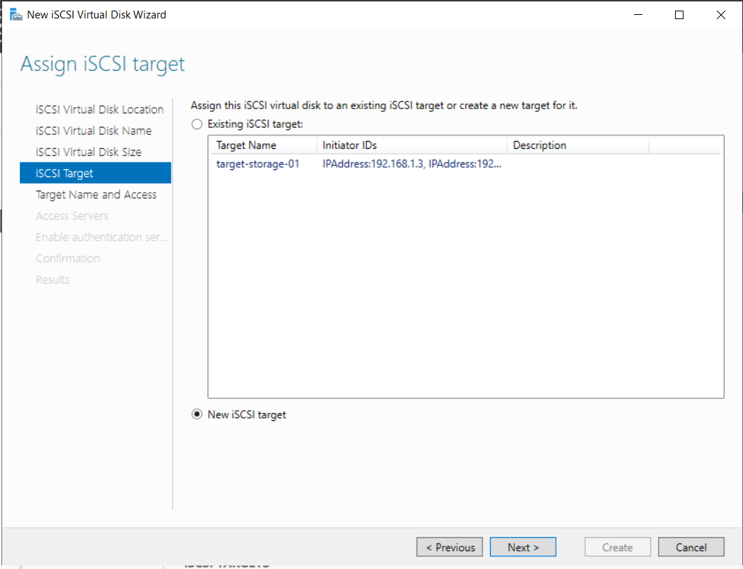
Step 2: Assign iSCSI Target
Select New iSCSI Target -> Next.
Target Name and Access -> Next
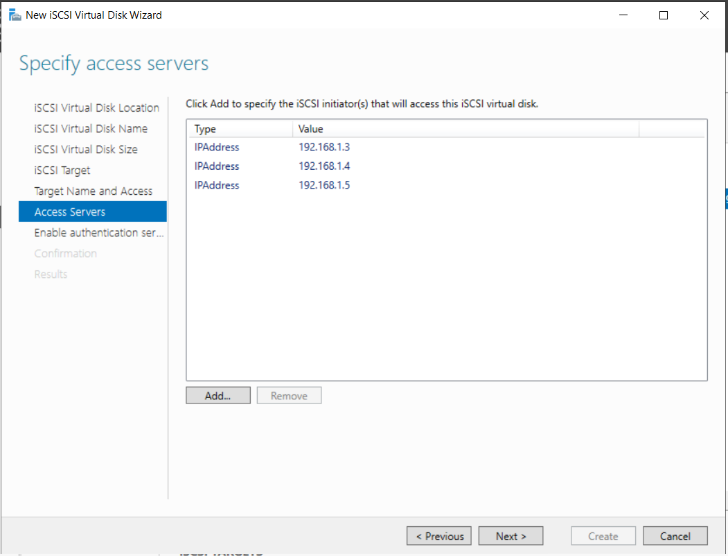
Step 3: Specify Access Servers
Click Add -> Select Enter a value for the selected type -> Type: IP Address.
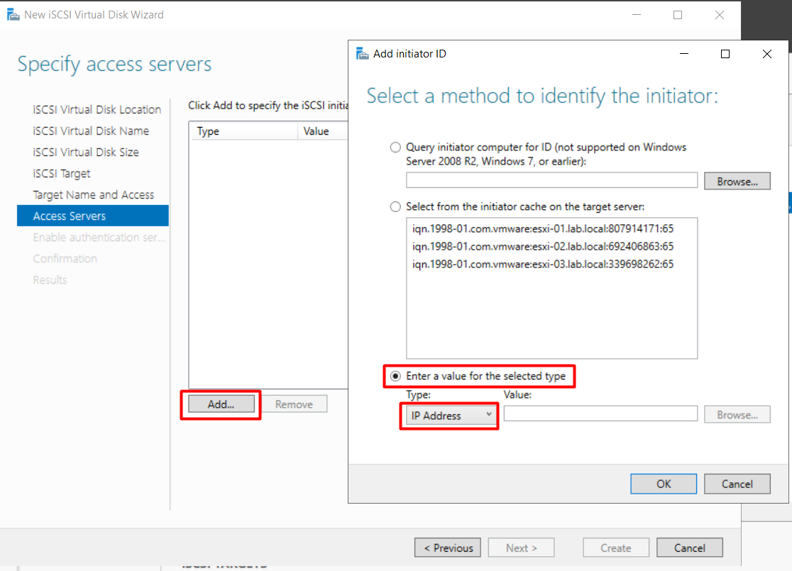
Add the IP addresses of all 3 ESXi hosts (192.168.1.3, 1.4, 1.5).
Enable authentication -> Next
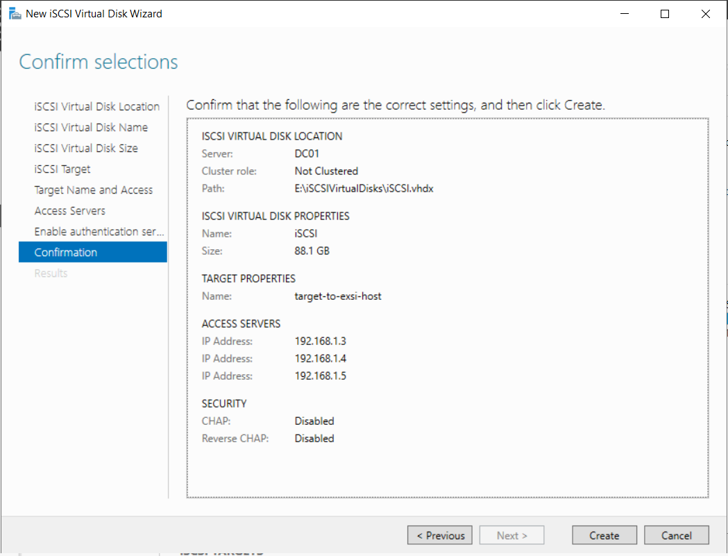
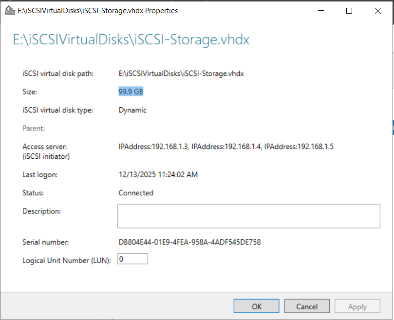
Step 4: Completion
Review settings and create. You should see the status “Completed”.
3. Deploying ESXi Hosts
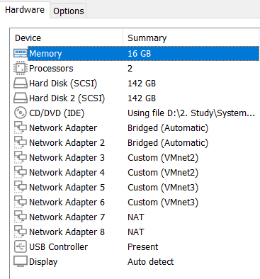
3.1. VM Settings for ESXi
For each ESXi host (01, 02, 03), configure the VM hardware:
- Memory: 16GB (recommended)
- Processors: 2
- Hard Disks: 142GB
- Network Adapters: Add multiple adapters for different networks (Mgmt, vMotion).
3.2. Network Configuration (DCUI)
Boot the ESXi installer. After installation, press F2 to Configure Management Network.
DNS Configuration:
- Primary DNS Server: 192.168.1.2 (IP of DC01)
- Hostname:
esxi-01.lab.local
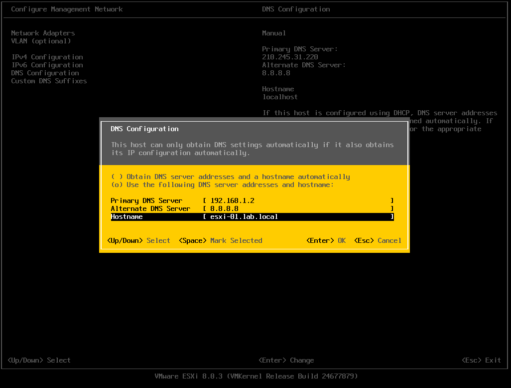
Custom DNS Suffixes: Enter lab.local.

Repeat these steps for ESXi-02 and ESXi-03.
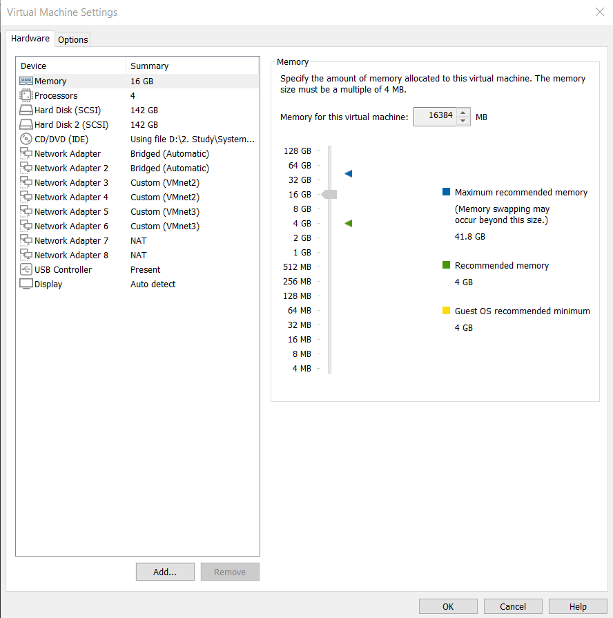
3.3. Special Setup for ESXi-03 (vCenter Host)
Since ESXi-03 will host the vCenter VM, assign it sufficient resources (e.g., 4 Processors).
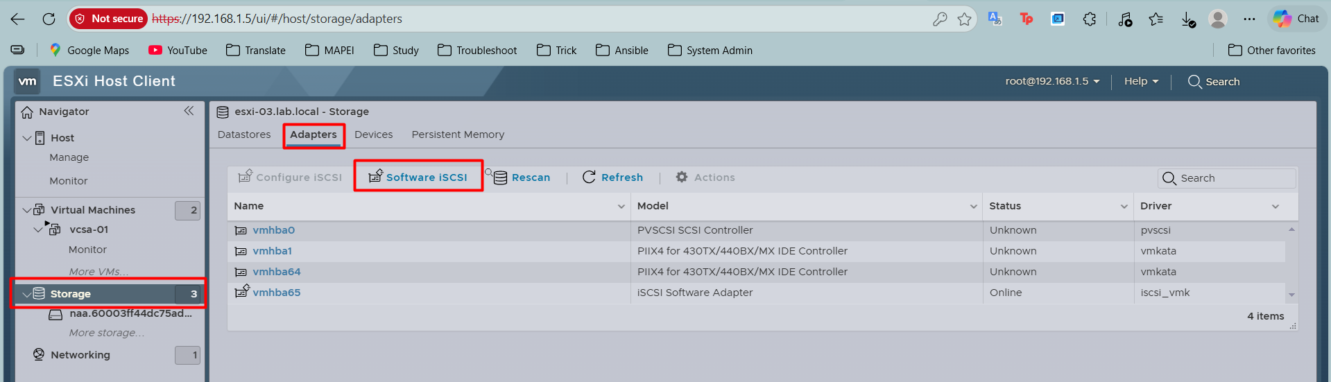
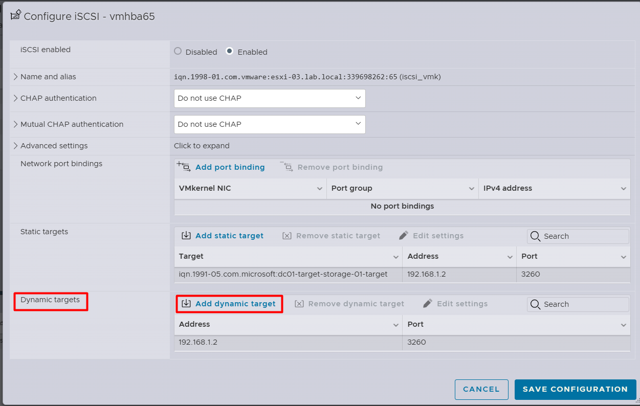
4. Configuring Shared Storage (iSCSI) on ESXi
Perform this on all hosts (ESXi-01, 02, 03).
- Login to ESXi Web Client.
- Go to Storage -> Adapters -> Software iSCSI.
- Enable iSCSI.
- Under Dynamic Targets, click Add dynamic target.
- Enter the IP of Windows Server:
192.168.1.2. - Click Save Configuration.
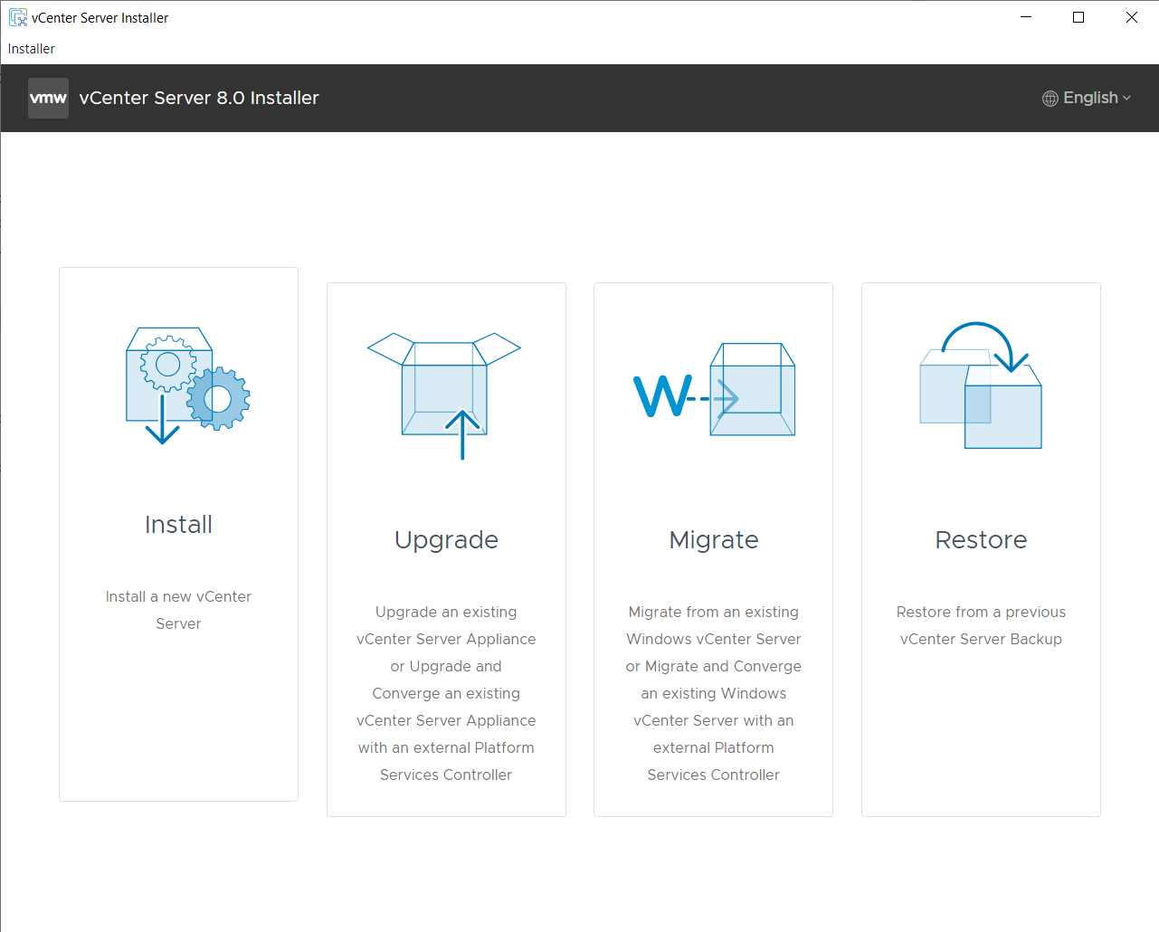
5. Deploying vCenter Server (VCSA)
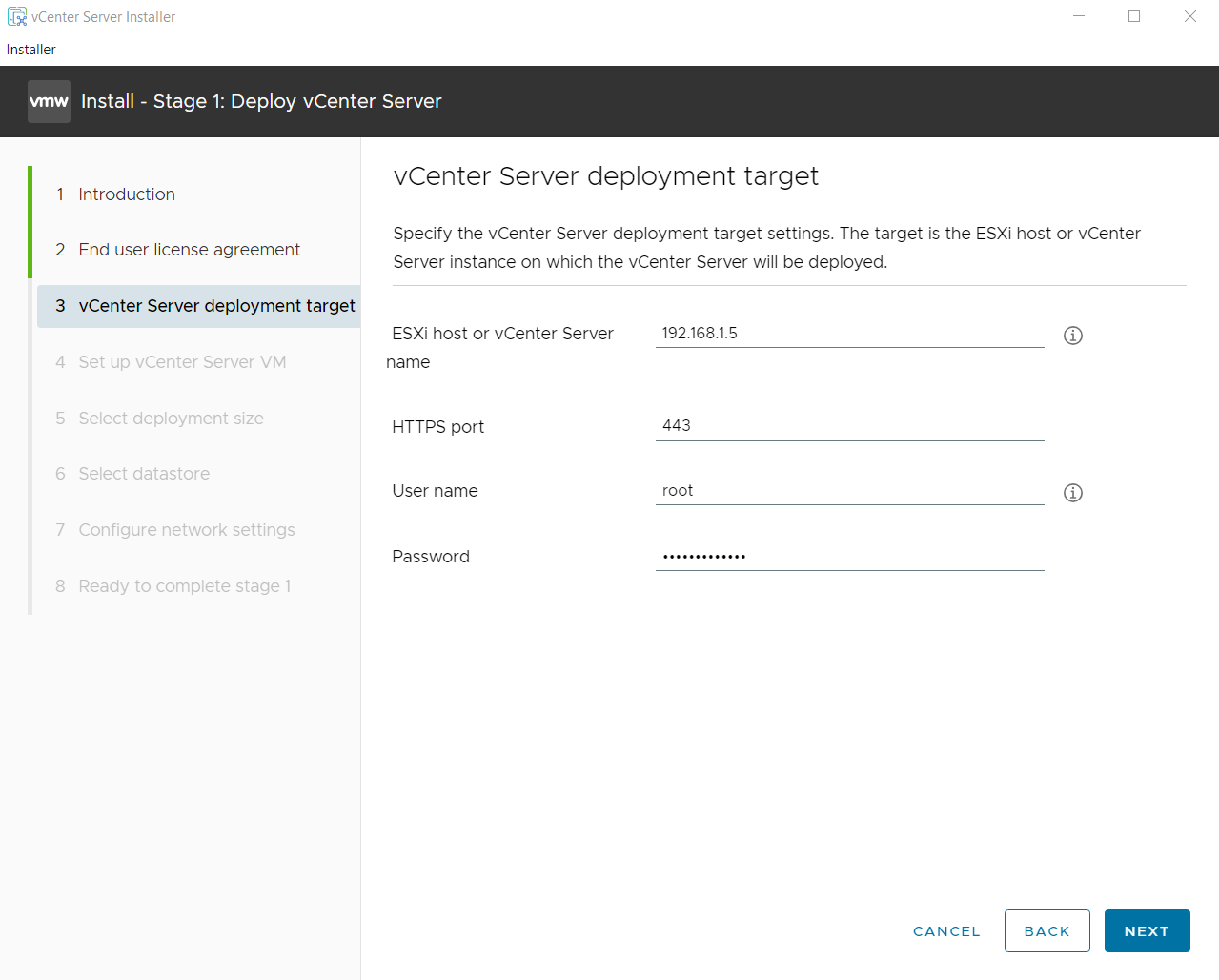
Stage 1: Deploy vCenter Server
Mount the VCSA ISO. Run `installer.exe` (found in `vcsa-ui-installer\win32`). Select Install.
Deployment Target: Enter IP of ESXi-03 (192.168.1.5), HTTPS port 443, User root, and password.
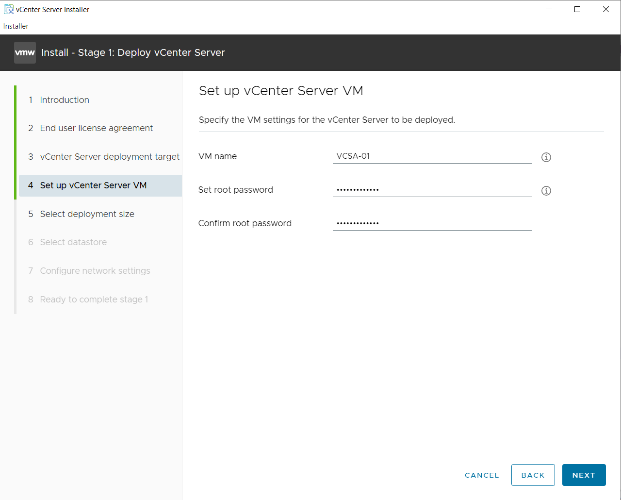
Set up VM: VM Name: VCSA-01. Set root password.
Deployment Size: Select Tiny (or Small) based on your resources.
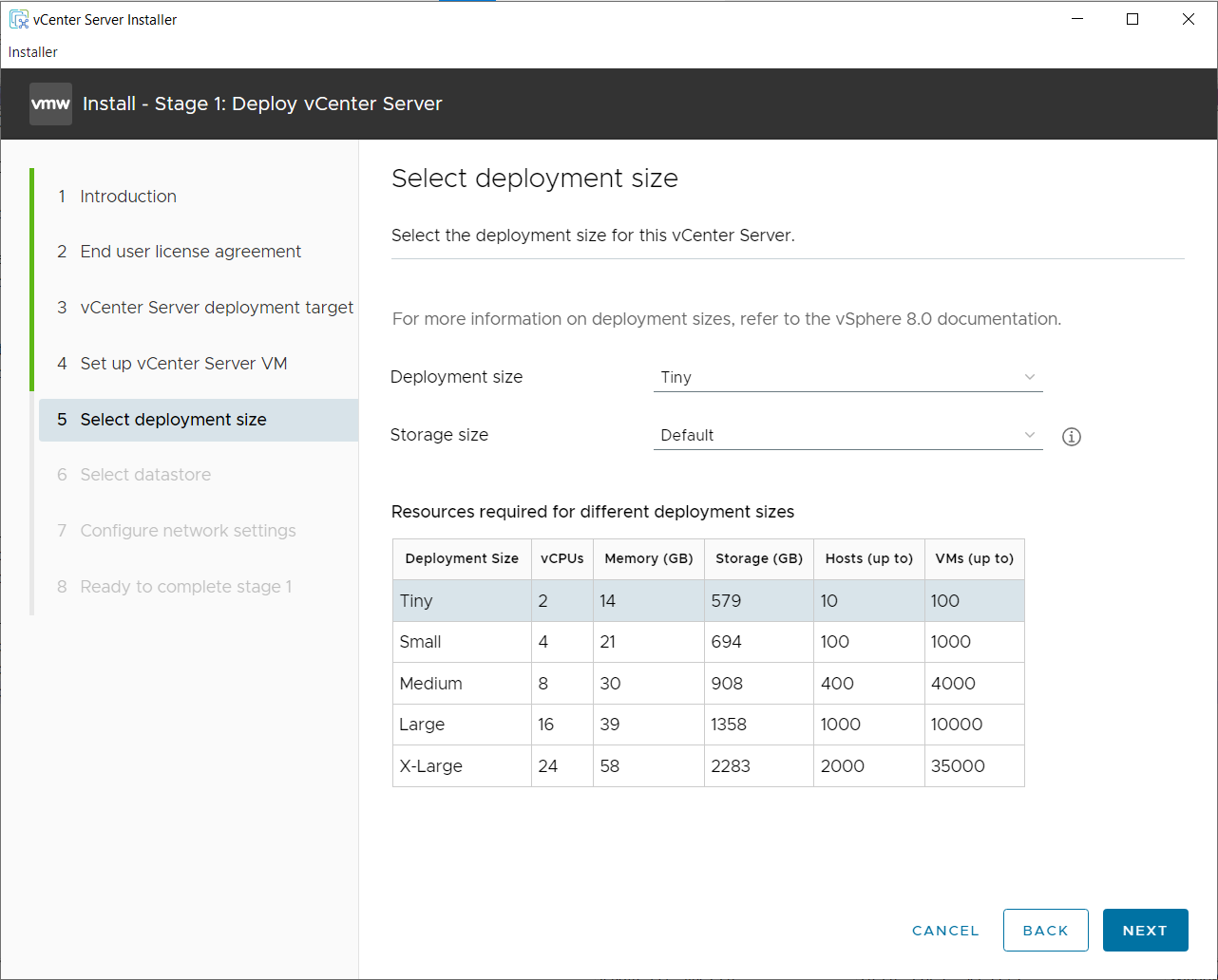
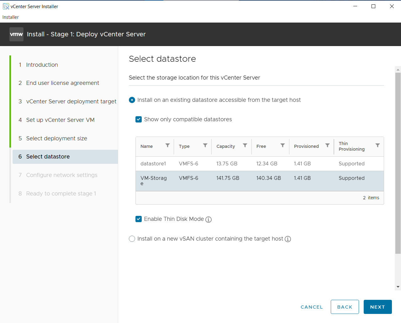
Select Datastore: Choose the local datastore created on ESXi-03.
Important Check Enable Thin Disk Mode to save space (initially occupies ~20-25GB).
Network Settings: Configure Static IP for vCenter (192.168.1.6).
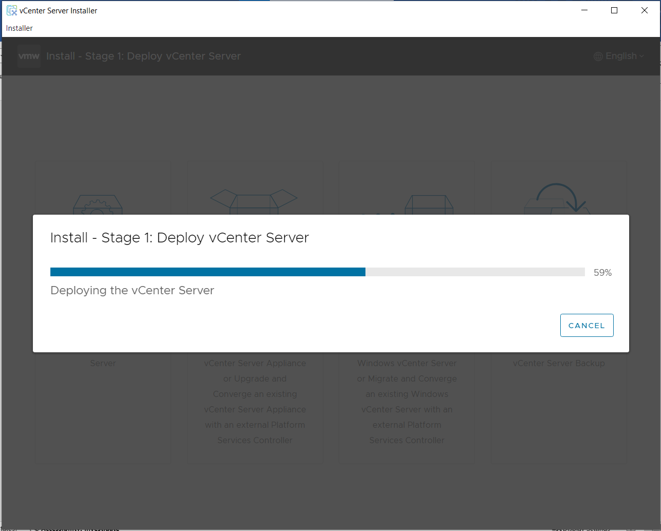
Wait for Stage 1 to complete.
Stage 2: Set Up vCenter Server
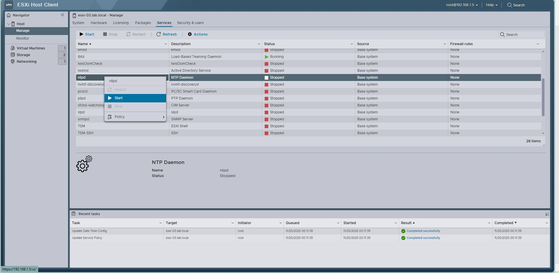
Prerequisite: NTP Setup on ESXi-03
Before proceeding, ensure ESXi-03 time is synchronized. Go to ESXi-03 -> Manage -> System -> Time & date -> Edit NTP Settings.
- Select Use Network Time Protocol.
- Service startup policy: Start and stop manually.
- NTP servers:
vn.pool.ntp.org.
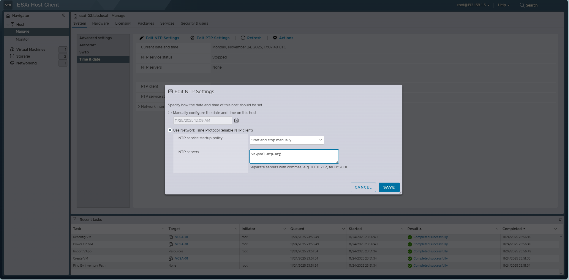
Start the ntpd service.
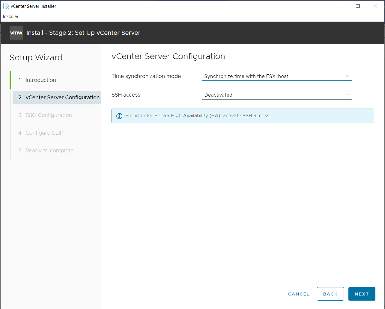
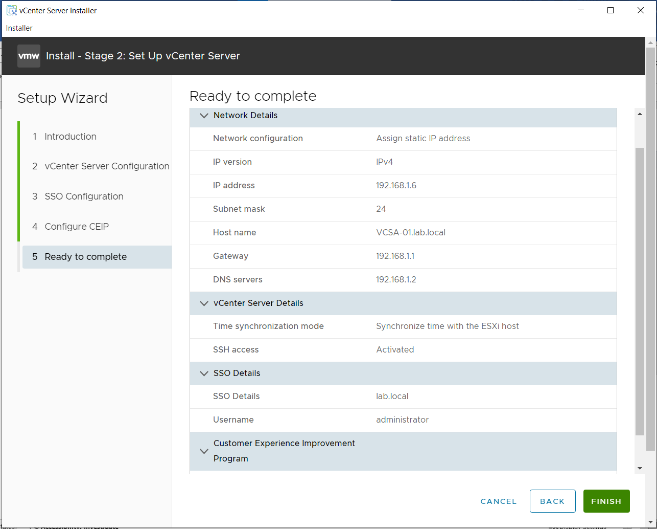
Proceed with Stage 2:
- Time synchronization: Sync with ESXi host.
- SSH access: Activated.
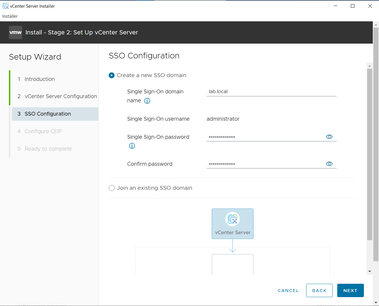
SSO Configuration: Domain: lab.local. Set Administrator password.
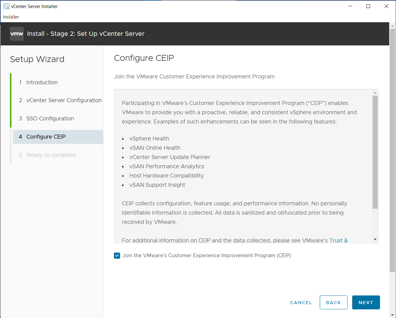
Configure CEIP -> Next
Ready to Complete
At DC01, add to host file or add to DNS Manager: 192.168.1.6 vcsa-01.lab.local
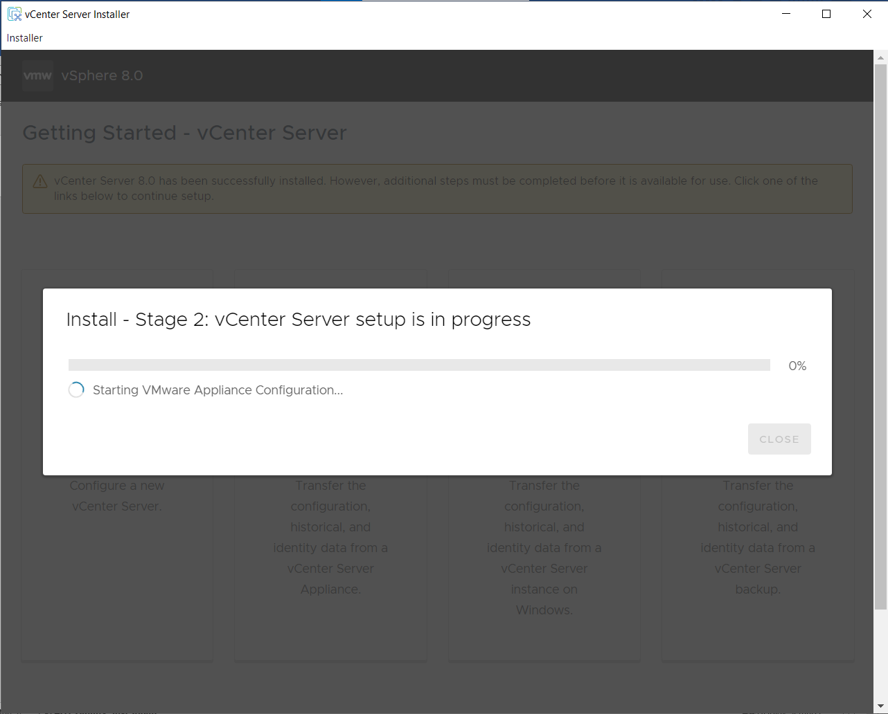
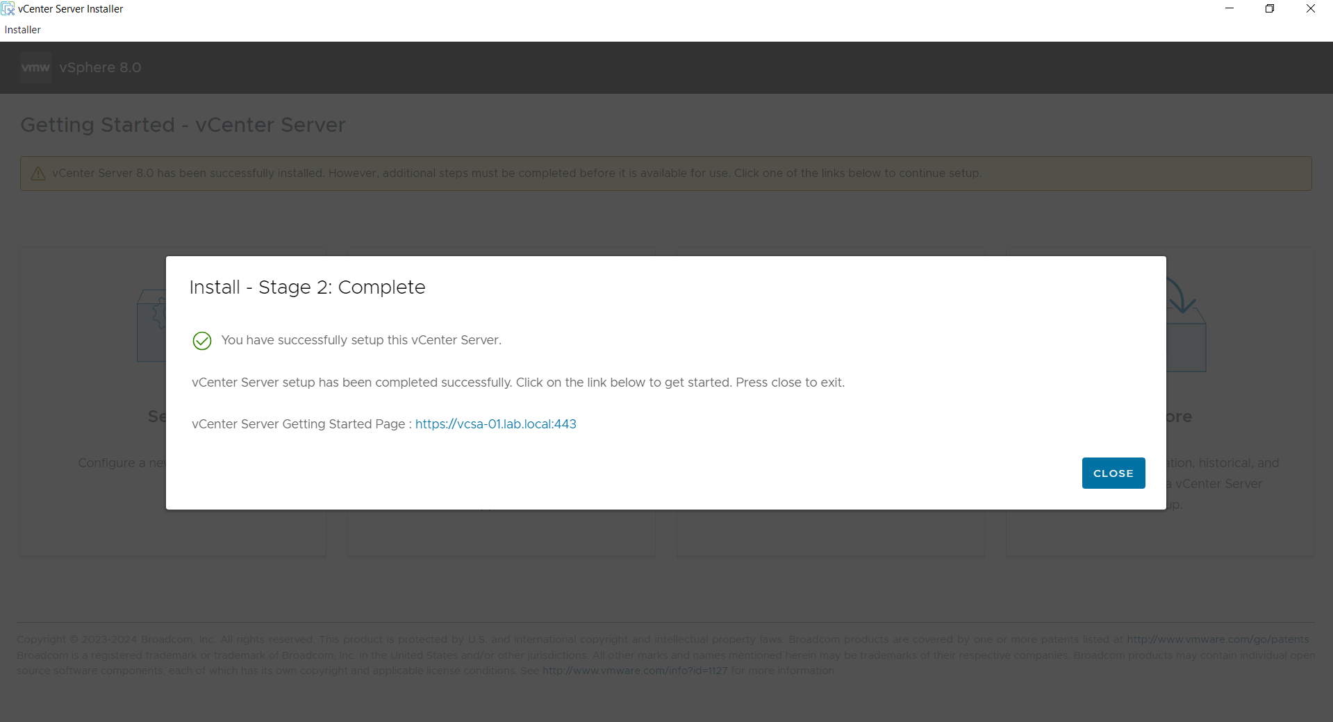
Finish and wait for completion.
6. Configuring Cluster (HA & DRS)
Log in to vSphere Client (https://vcsa-01.lab.local or IP).
Step 1: Create DataCenter
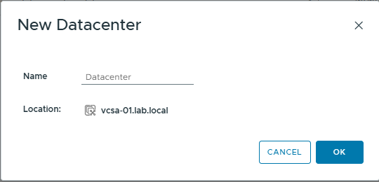
Right-click vCenter -> New Datacenter -> Name it (e.g., lab.local).
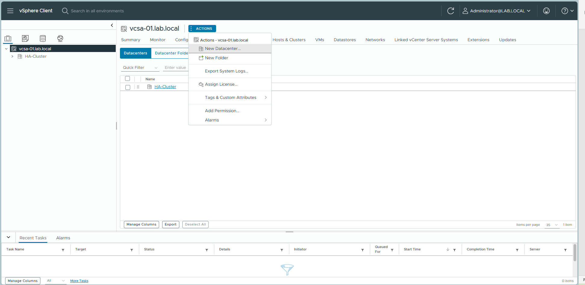
Input Datacenter Name
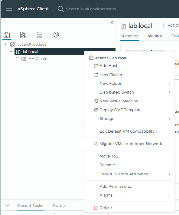
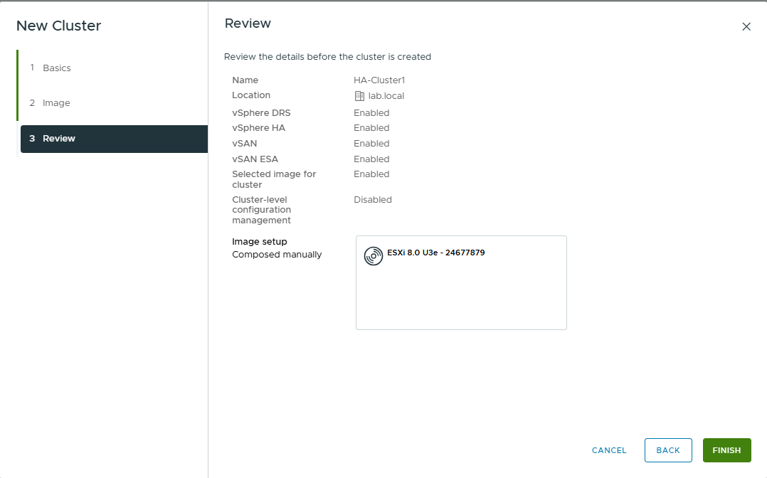
Step 2: Create Cluster
Right-click Datacenter lab.local -> New Cluster.
Enable vSphere DRS and vSphere HA.
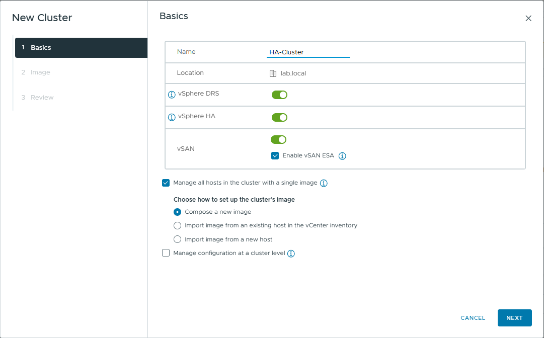
Image Setup: Skip or select default ESXi version.
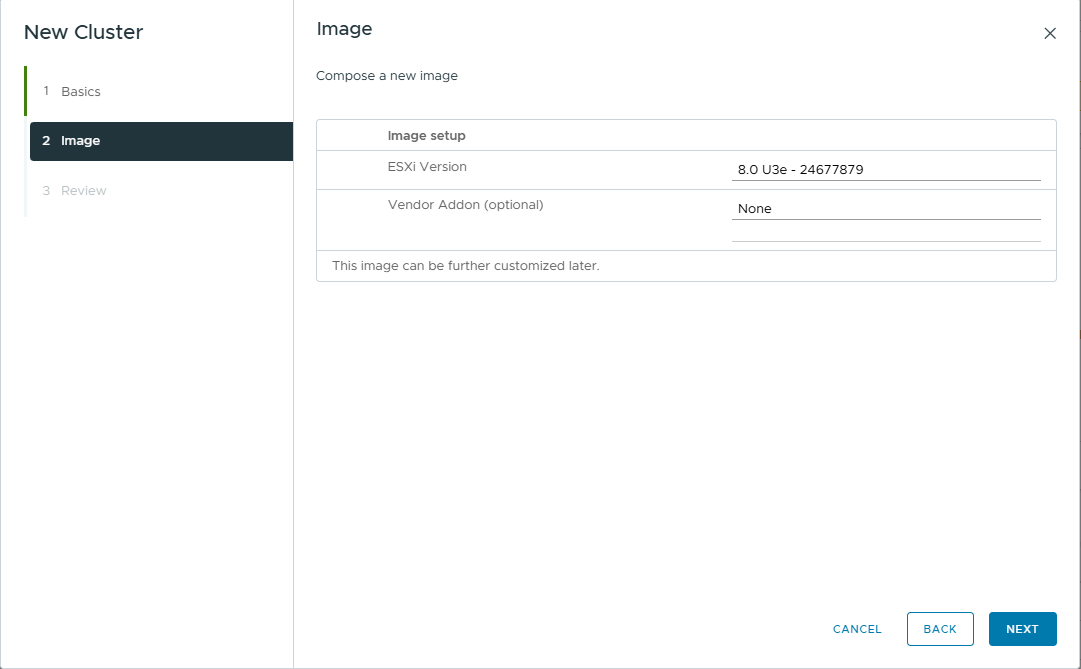
Review and Finish
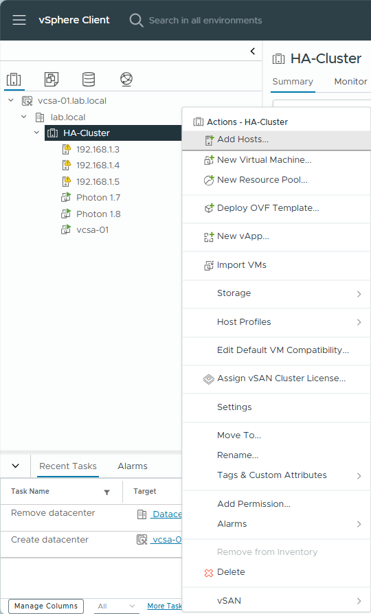
Step 3: Add Hosts to Cluster
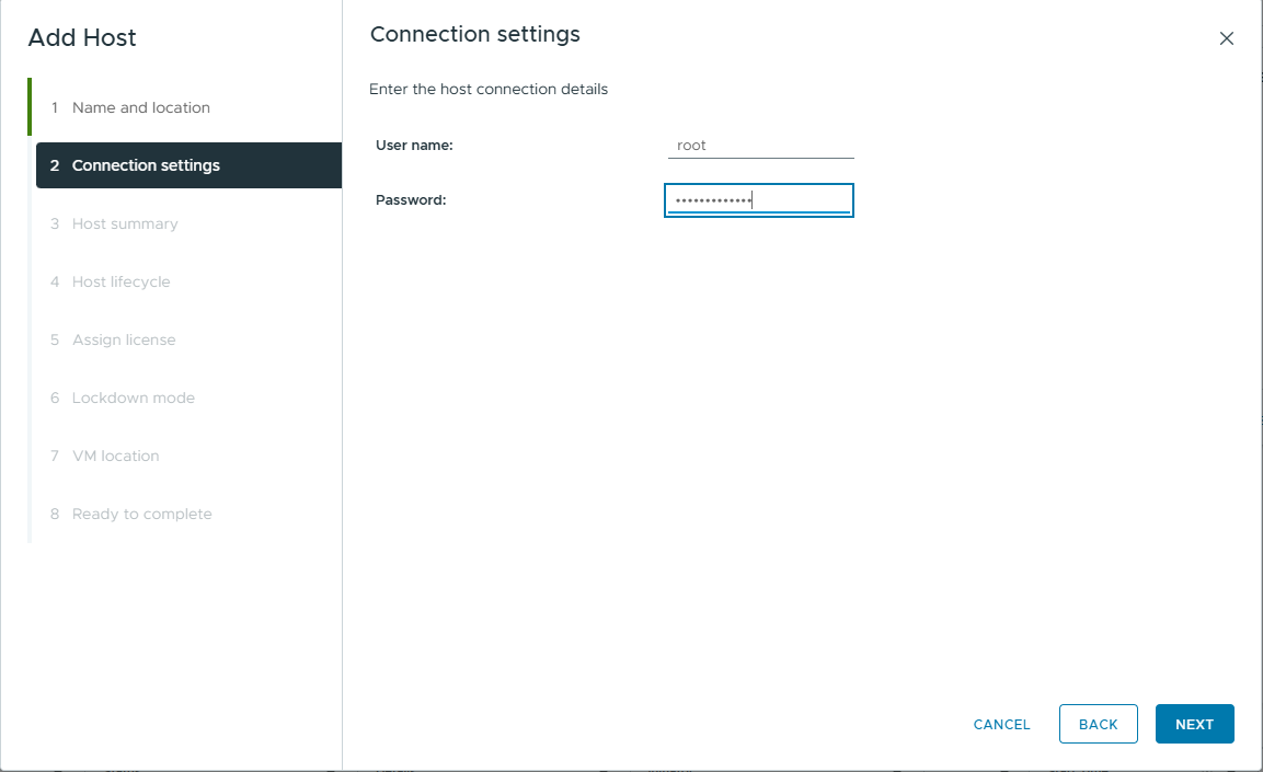
Right-click the new Cluster -> Add Hosts.
Enter IP (192.168.1.3).
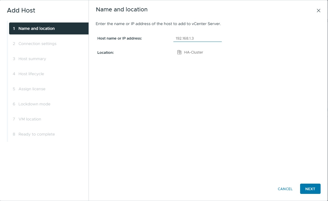
Enter User (root), and Password.
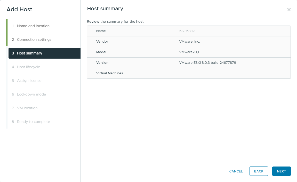
Host Summary -> Next
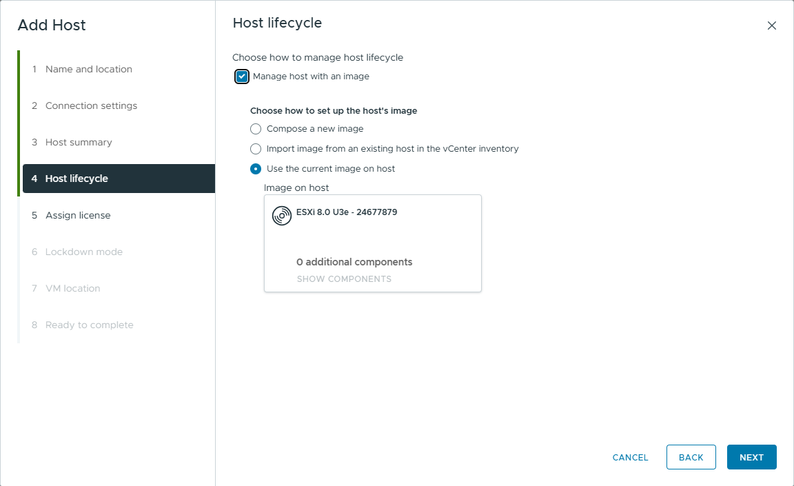
Host lifecycle
Click manage host with an image -> Choose Use the current image on host -> Next
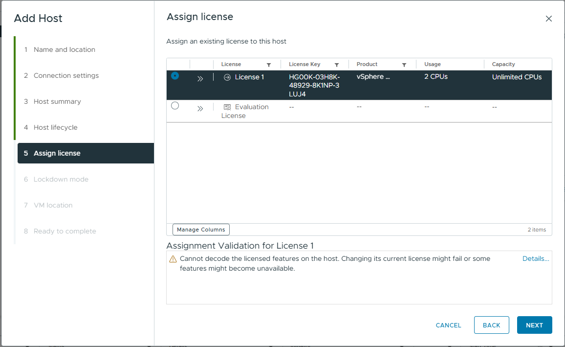
Assign license -> Select license -> Next
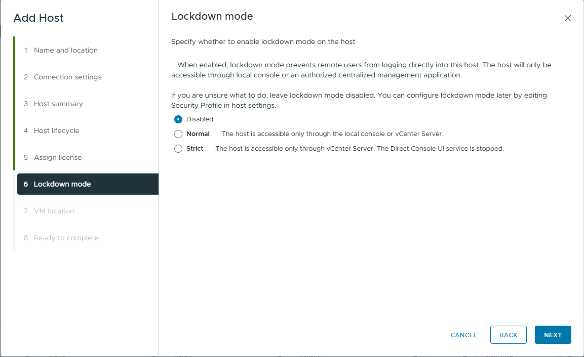
Lockdown mode -> Disable -> Next
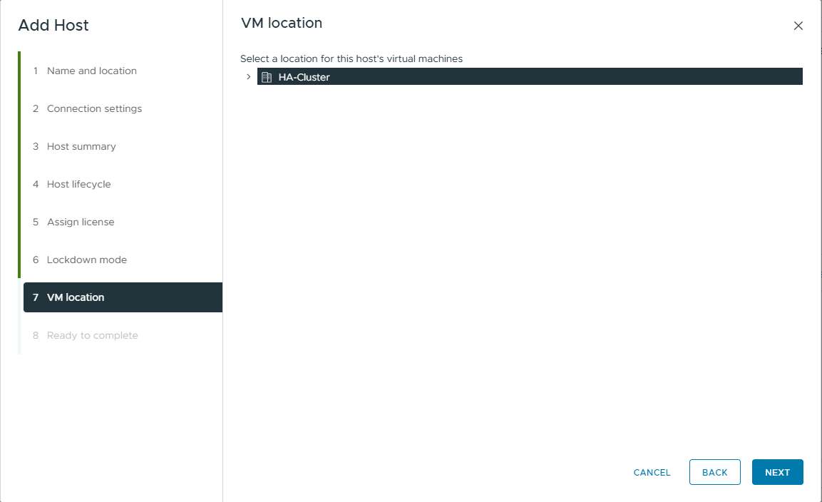
VM location
Choose location and Next
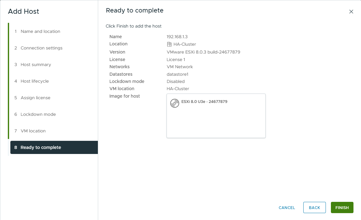
Ready to complete
Repeat for ESXi-02 and ESXi-03. The result should look like this:
EXSI-01
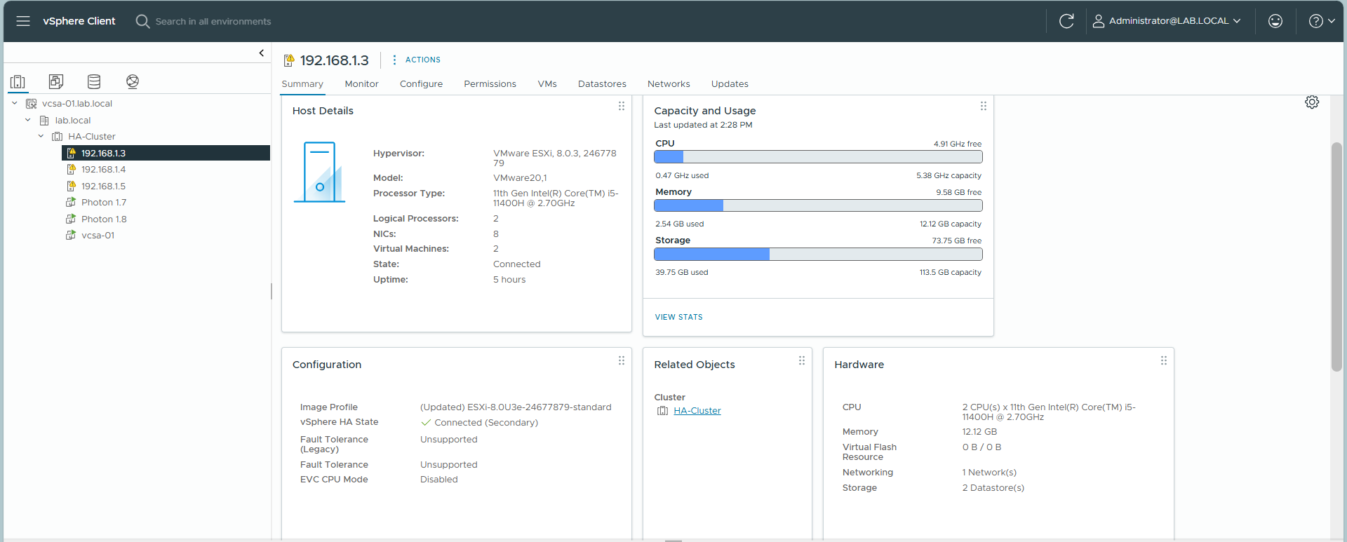
EXSI-02
EXSI-03
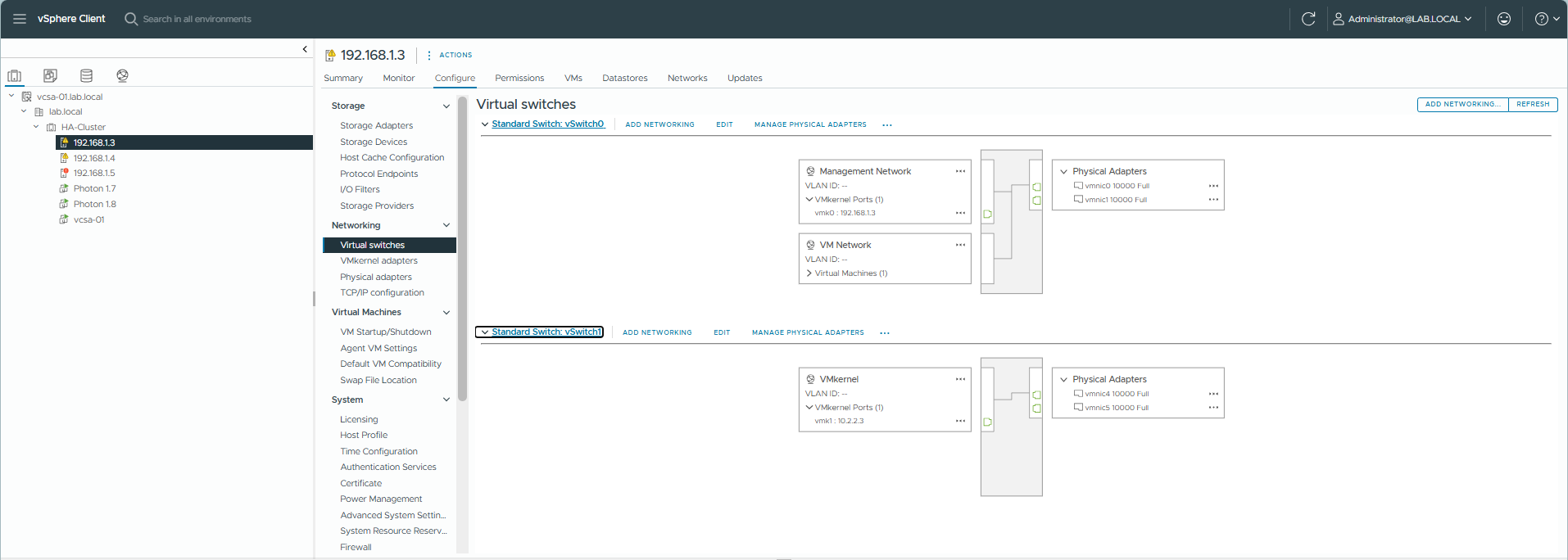
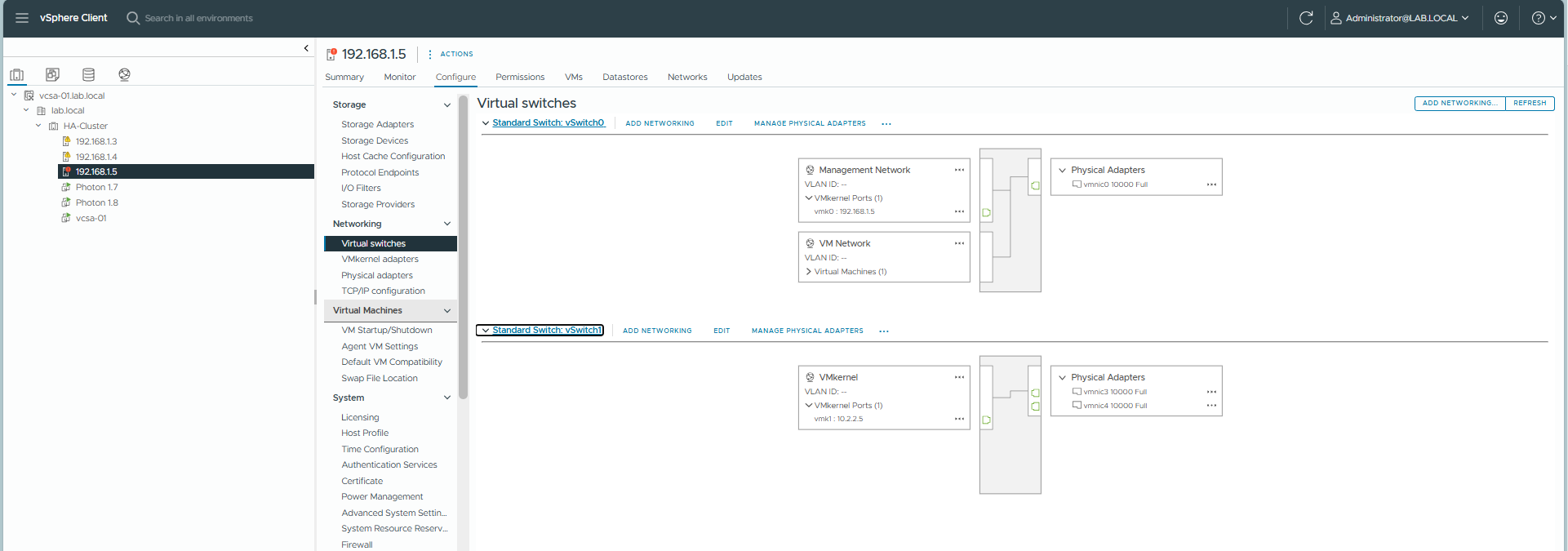
7. Configuring vMotion Network
For Live Migration to work, you must configure a VMkernel adapter enabled for vMotion on each host.
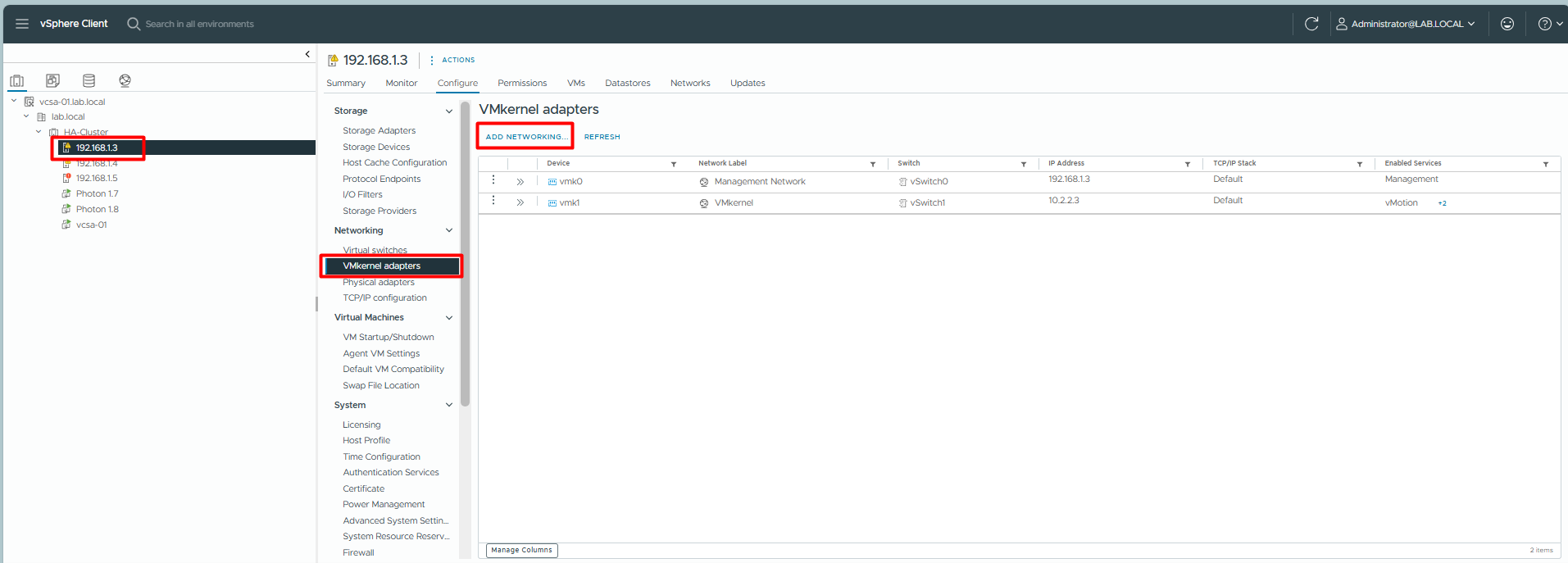
Step 1: Add Networking
Select Host (e.g., 192.168.1.3) -> Configure -> VMkernel adapters -> Add Networking.
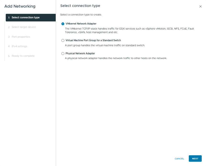
Step 2: Select Connection Type
Choose VMkernel Network Adapter.
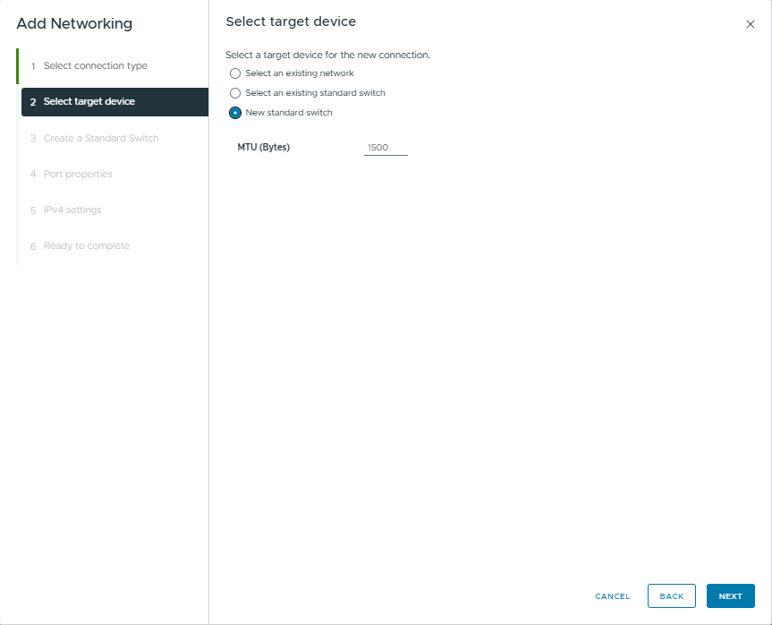
Step 3: Select Target Device
Select New standard switch (since we are creating a dedicated switch).
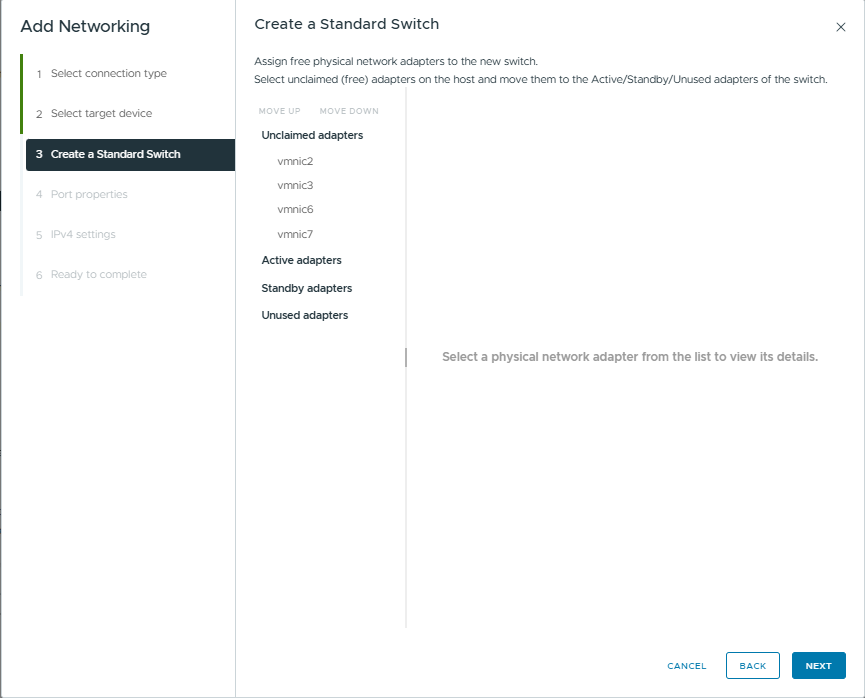
Create a Standard Switch: Add the unused adapters (e.g., vmnic2, vmnic3) to Active adapters.
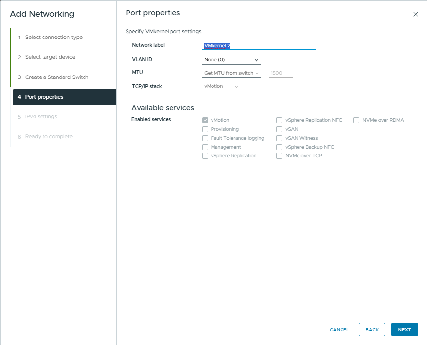
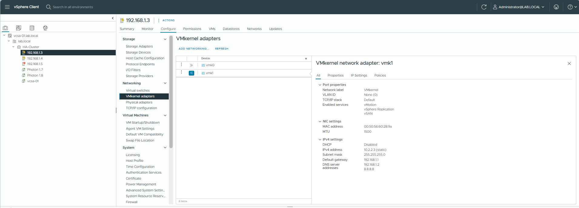
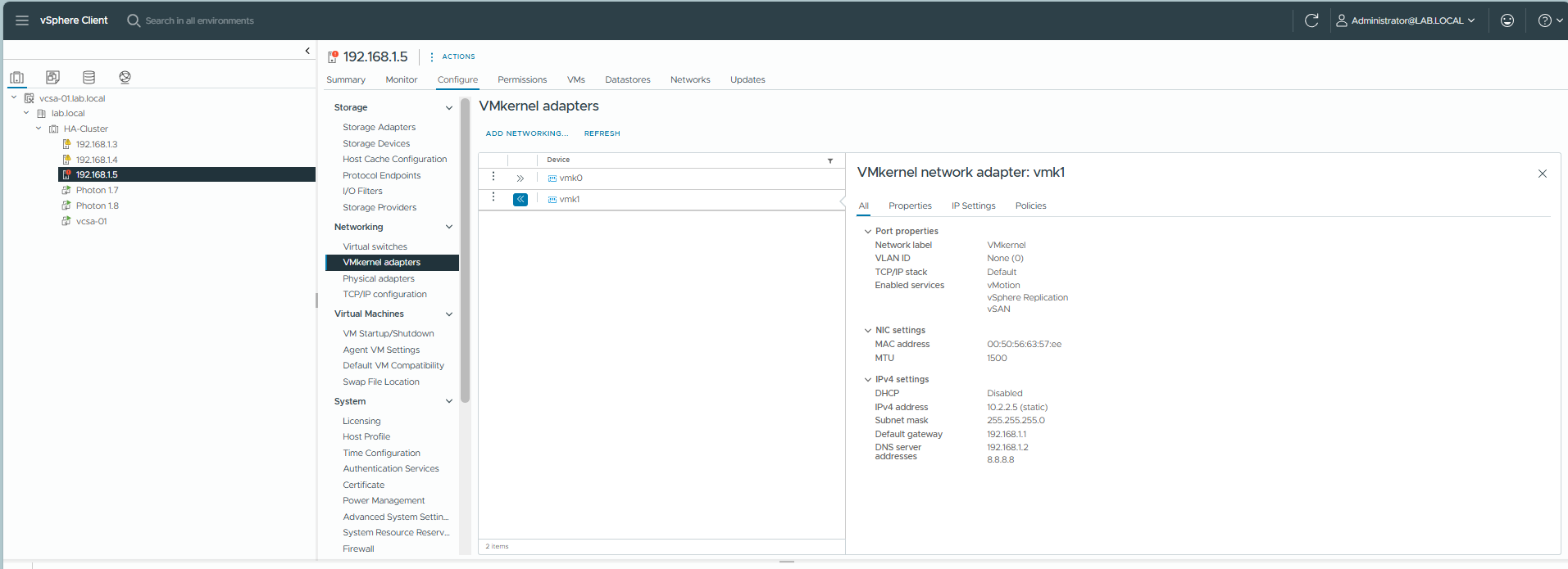
Step 4: Port Properties
Network Label: VMkernel 2 (or vMotion).
TCP/IP stack: Select vMotion.
Enabled services: Check vMotion.
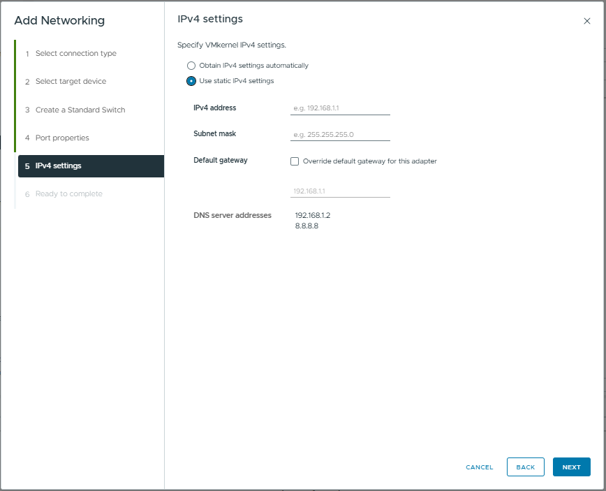
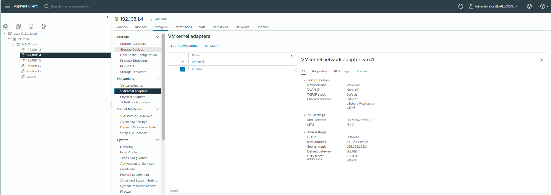
Step 5: IPv4 Settings
Use static IPv4 settings as per the plan (e.g., 10.2.2.3 for Host 1). Use a separate subnet from Management network.
Repeat for all hosts (ESXi-02: 10.2.2.4, ESXi-03: 10.2.2.5). Ensure results look like this:
ESXi-01 Result:
ESXi-02 Result:
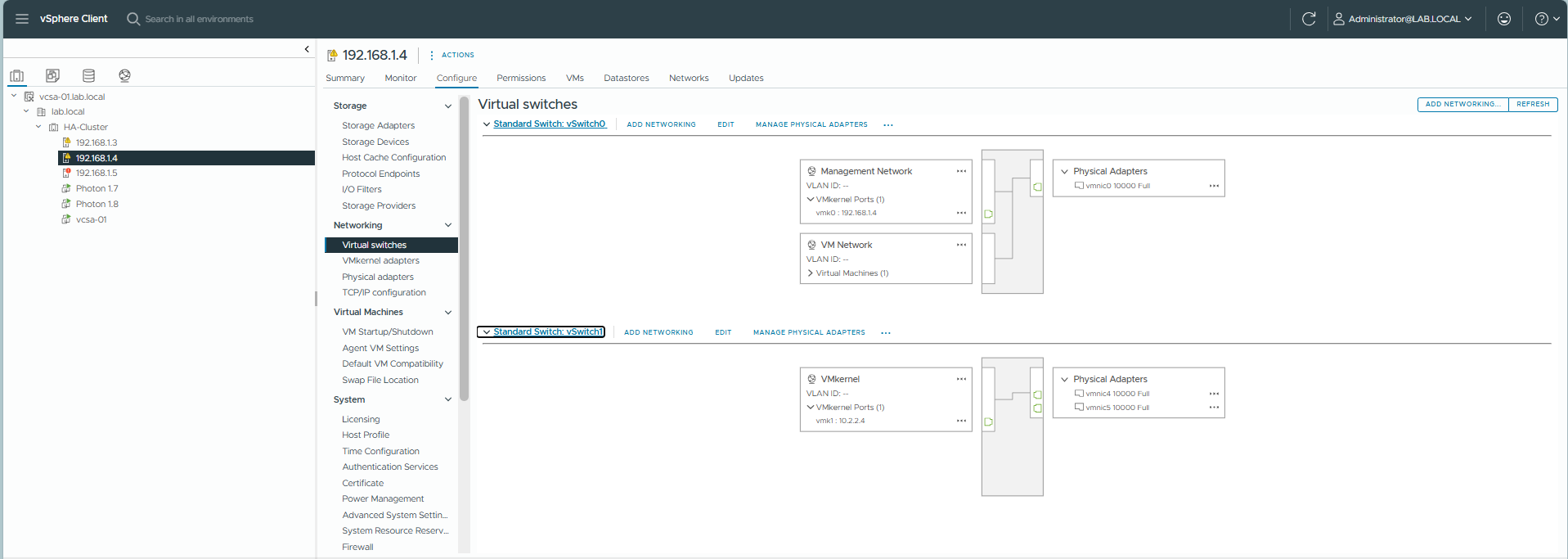
ESXi-02 Result:
8. Validation: Deploy VM, Testing HA & vMotion
8.1. Preparation: Deploying a Test VM
We will prepare 2 VMs on ESXi hosts 192.168.1.3 and 192.168.1.4. Let’s create a “Photon” VM.
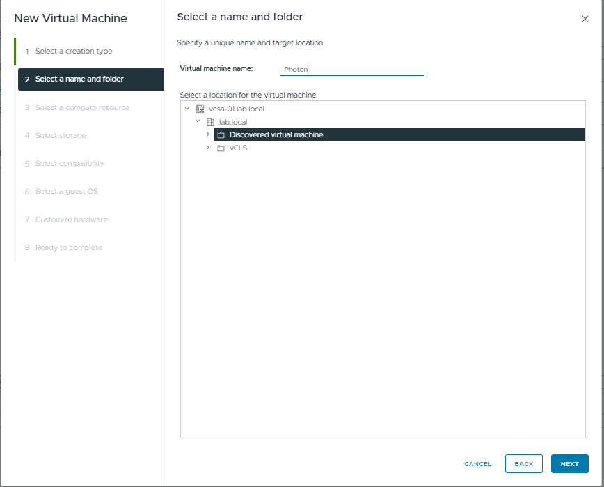
Step 1: Right-click Cluster -> New Virtual Machine.
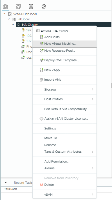
Step 2: Select Create a new virtual machine -> Next.
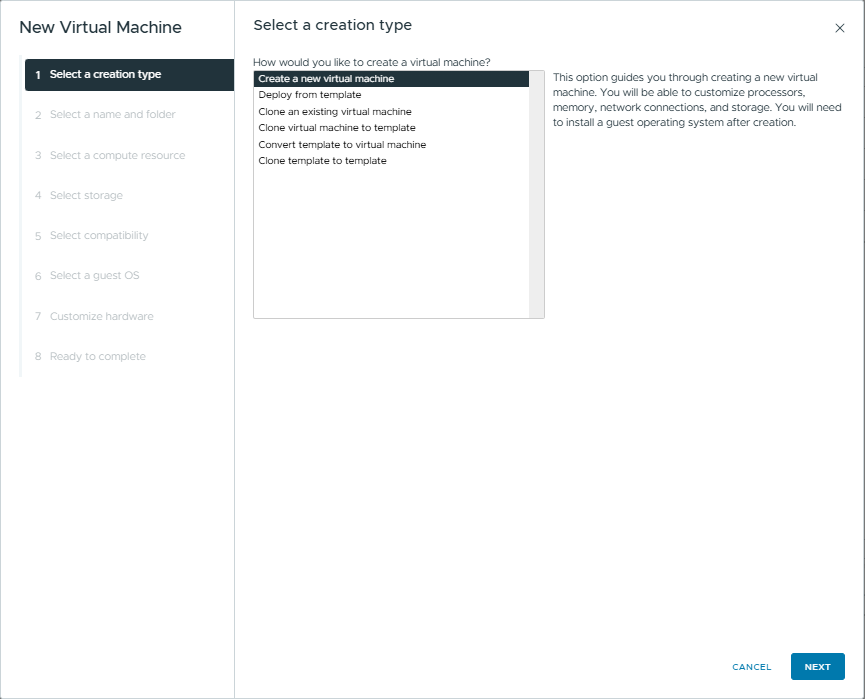
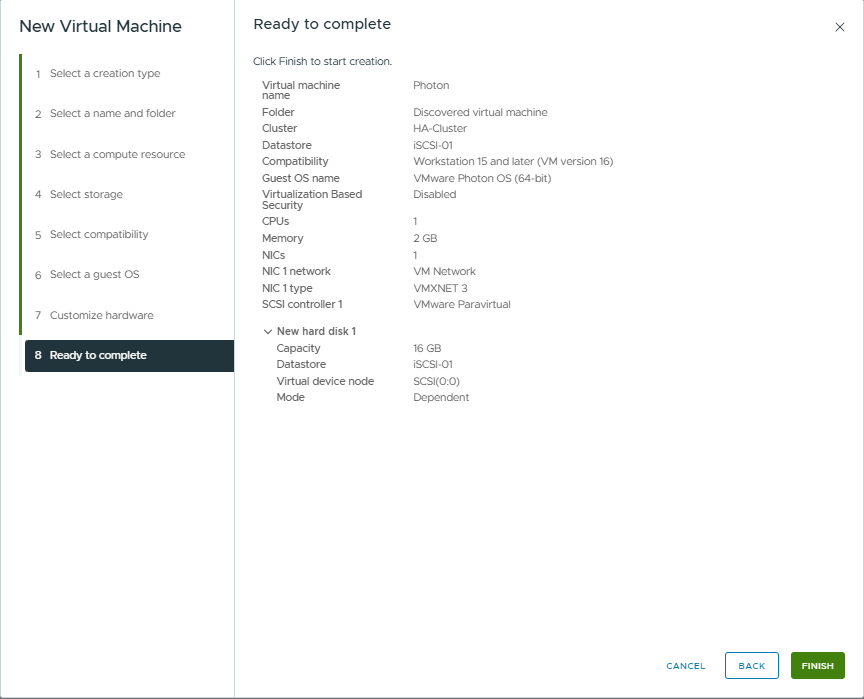
Step 3: Name: Photon. Select location.
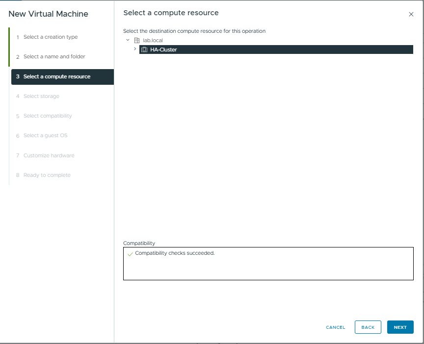
Step 4: Select compute resource (Choose Cluster or specific Host).
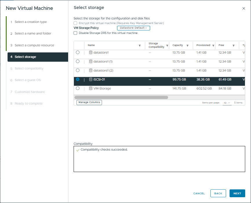
Step 5: Select Storage. Choose the Shared Storage (iSCSI-01).
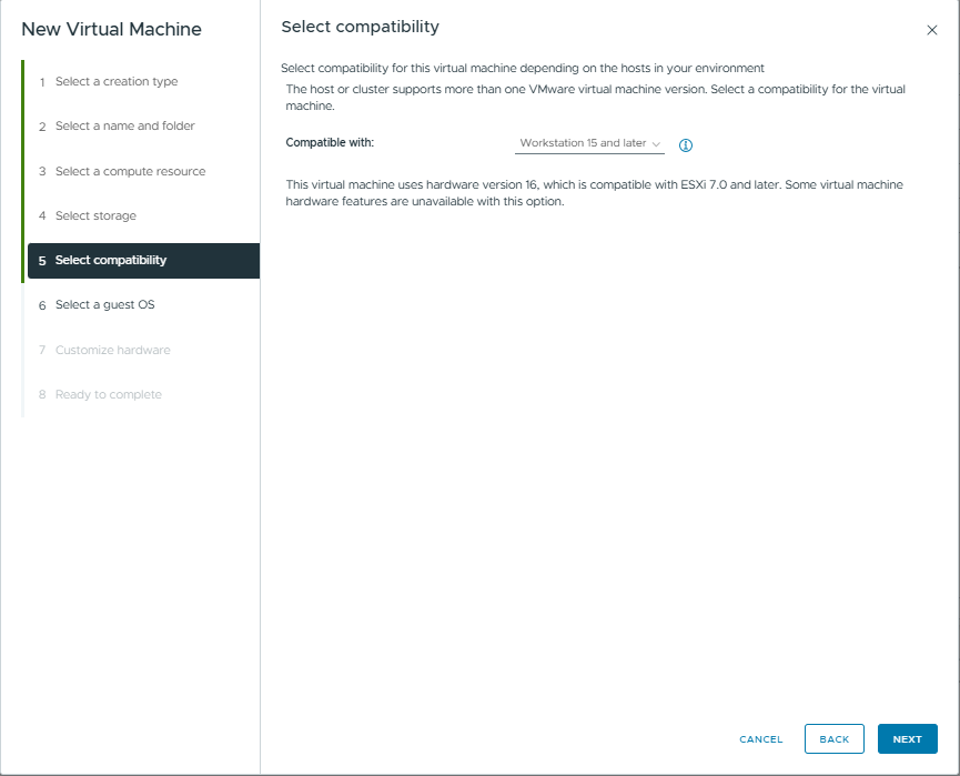
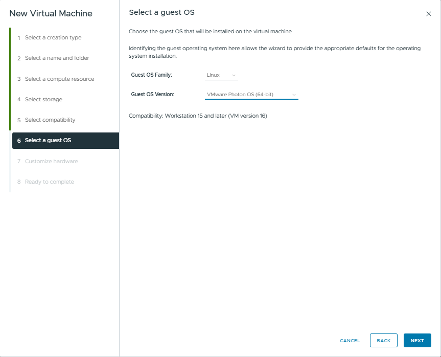
Step 6: Compatibility: Workstation 15 and later
Step 7: Guest OS: Linux, VMware Photon OS (64-bit).
Step 8: Customize Hardware. Ensure CD/DVD connects to Datastore ISO file. Tick “Connect At Power On”.
8.2. Testing High Availability (HA)
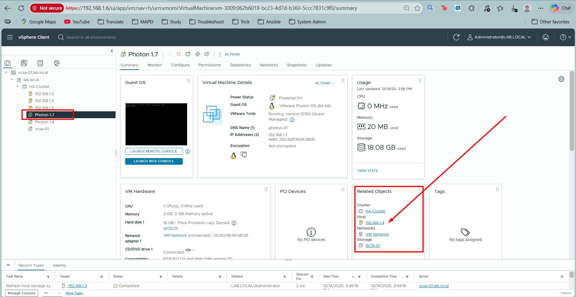
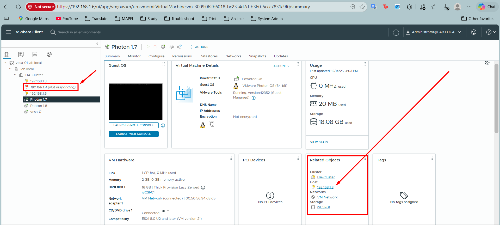
Scenario: Check vMotion capability on Photon 1.7 (IP: 192.168.1.7) running on ESXi-02 (IP: 192.168.1.4).
Action: Power Off ESXi-02 (simulate physical server failure).
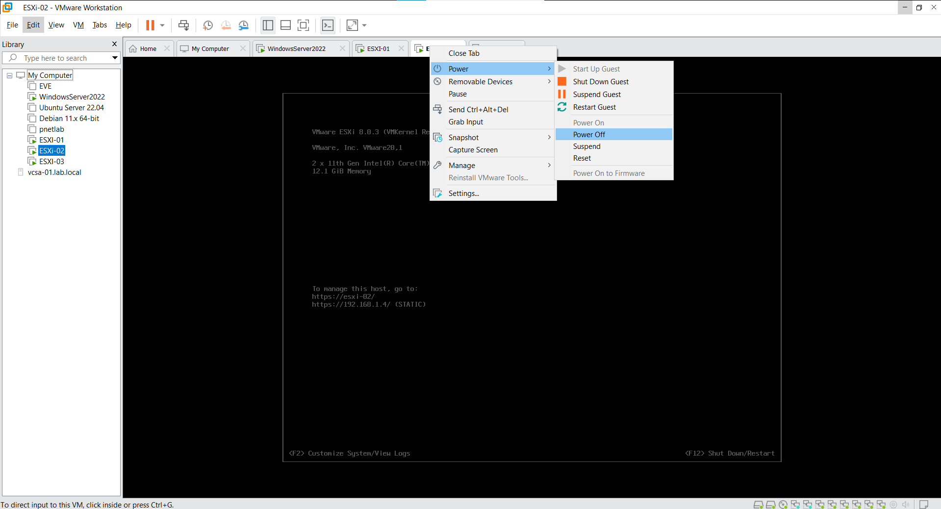
Result: vCenter detects 192.168.1.4 as (Not responding). The VM “Photon 1.7” is automatically restarted on a healthy host (ESXi-01 / 192.168.1.3).
8.3. Testing vMotion
Scenario: Migrate “Photon 1.7” from ESXi-01 (192.168.1.3) to ESXi-02 (192.168.1.4) while it is running.
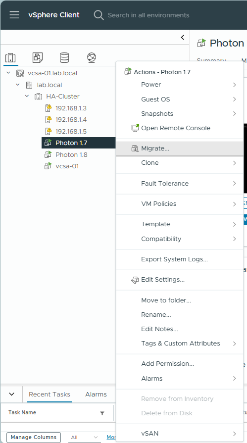
Step 1: Right-click VM -> Migrate.
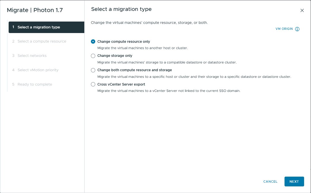
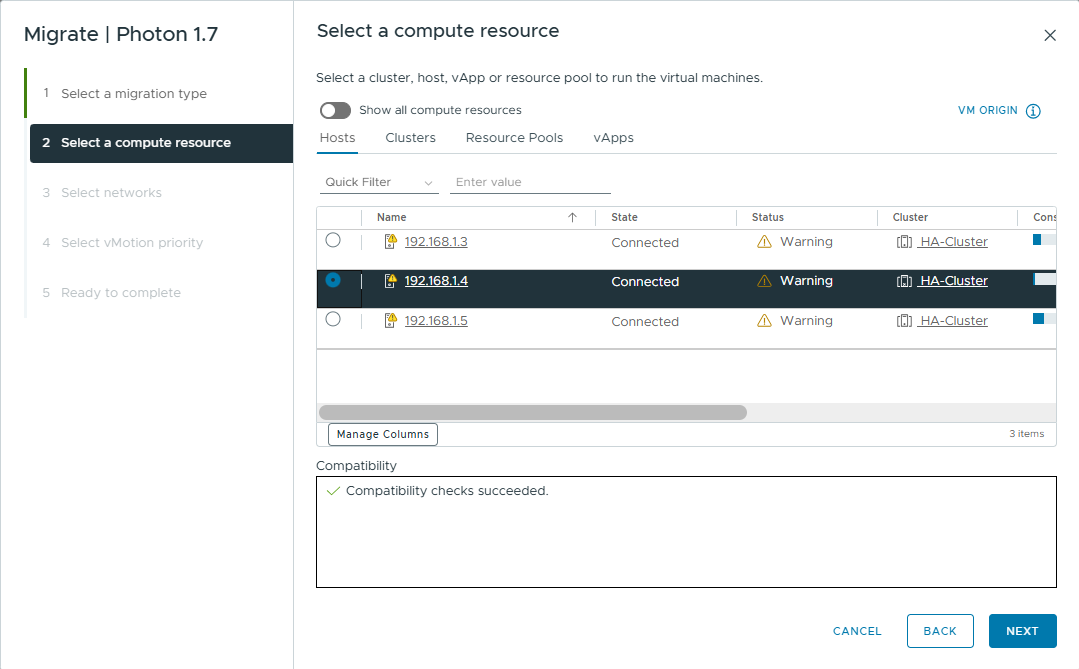
Step 2: Select Change compute resource only.
Step 3: Select Destination Host (ESXi-02 / 192.168.1.4).
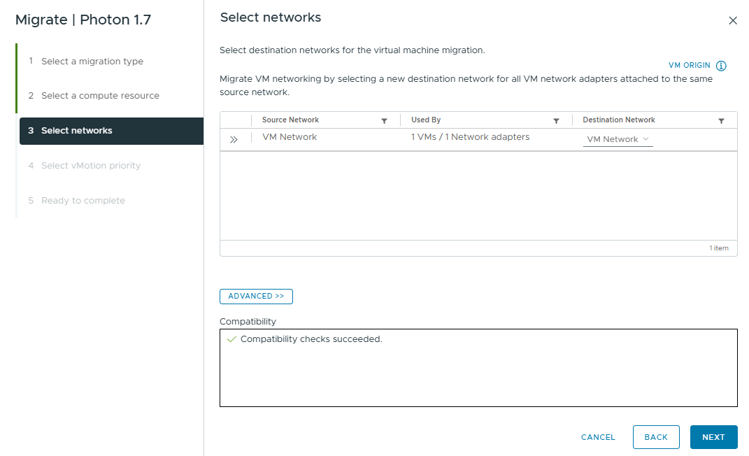
Step 4: Select Networks (usually leave default “VM Network”).
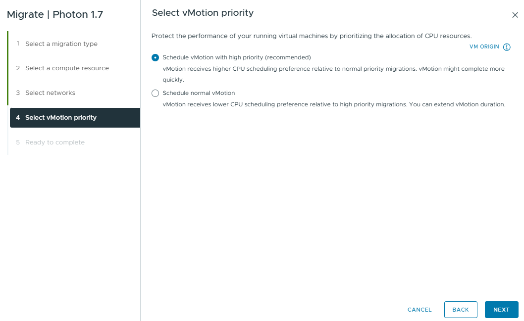
Step 5: Select Priority: Schedule vMotion with high priority.
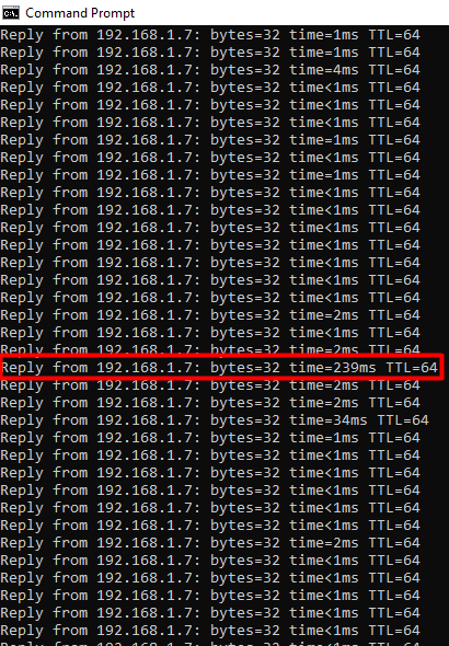
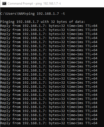
Step 6: During migration, run a continuous ping command: ping 192.168.1.7 -t.
Reply from 192.168.1.7: bytes=32 time=6ms TTL=64
Reply from 192.168.1.7: bytes=32 time=1ms TTL=64
Step 7: Click Finish to start migration.
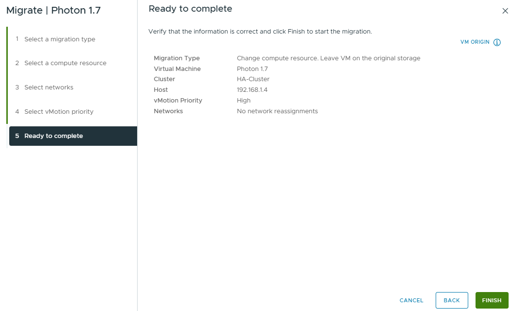
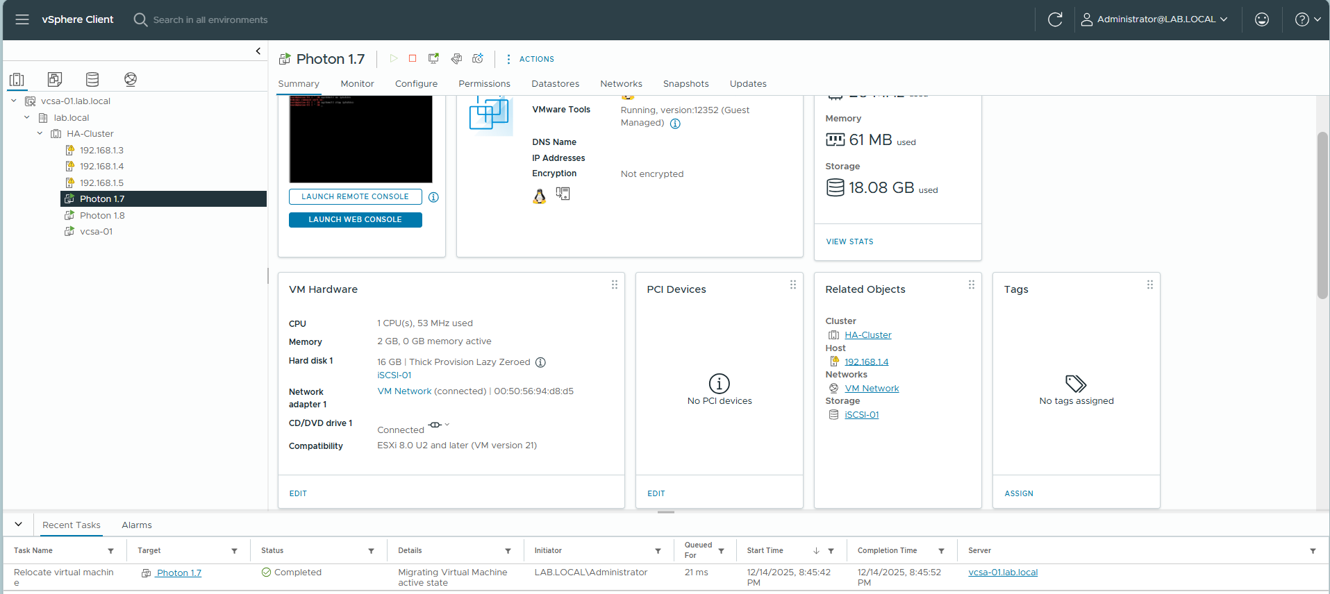
Step 8: Monitor the “Relocate virtual machine” task in Recent Tasks.

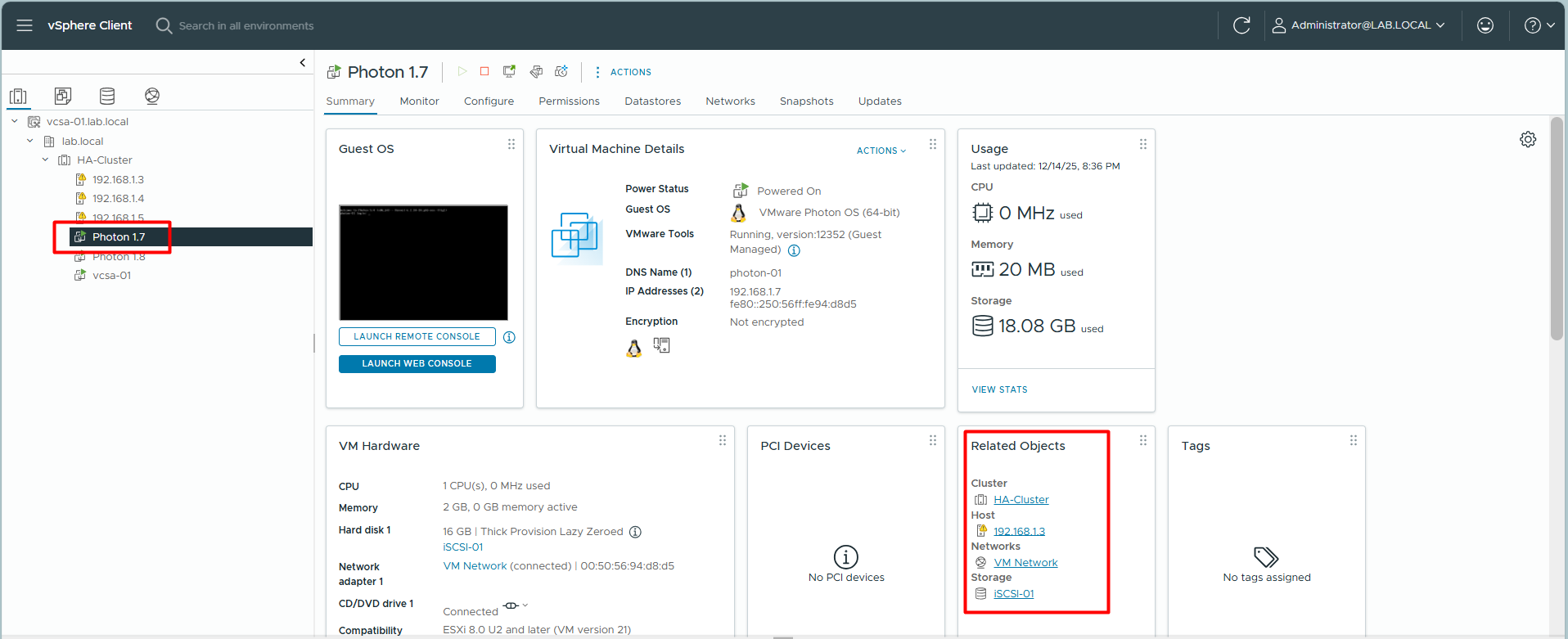
Final Result: The VM is now running on Host 192.168.1.4.
Ping Check: Zero packet loss. You may see a slight latency spike (e.g., 239ms) during the switchover, but no timeout.